Operation, Led indicators – Inovonics FA575X User Manual
Page 2
FA575X Installation Instructions
Page 2 of 4
Rev. 1.00 F575X_V1.FM 08/24/2000
Operation
Power supply: A 14VAC transformer must be provided by the user to power the FA575.
Backup battery: An optional 1.2AH battery can be mounted in the FA575 enclosure.
Low voltage detection: The repeater will report low voltage if the supply voltage (either primary or backup)
causes its DC input voltage to drop below its low voltage threshold.
• AC power failure will not be reported directly—the system will detect inactivity if repeater power is off for
the duration of the supervision window. ‘
Supervision: The repeater should be programmed to send check-in signals to the receiver, but can operate
unsupervised.
To program for supervision: When programming the system panel to supervise the repeater, the repeater
point should be programmed as a 24-hour point. This is because the repeater may be processing signals from
24-hour points and should be given this same level of point status monitoring.
When programming the repeater for supervision, it is necessary to program the repeater to send check-in sig-
nals. All other programming options other than check-in times (like normally open versus normally closed, and
presence or absence of EOL resistor) will be ignored. Repeater programming is accomplished by connecting a
programming cable to the programming header on the repeater, setting the appropriate check-in time when
prompted by the panel or receiver display device, and pressing the repeater’s Reset button. (See panel or
receiver programming or installation manuals for more specific information.)
Test Button: The Test Button is used only in unique OEM applications.
Tamper: Case tamper is provided.
•
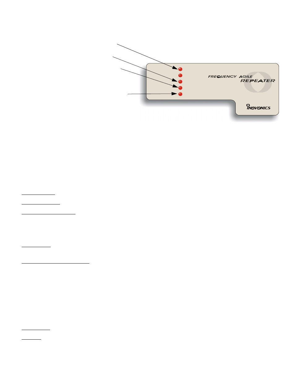
"AC POWER" and "BACKUP POWER" LEDs show
repeater power source.
•
"DECODING" indicates that the repeater is
receiving RF energy.
•
"TRANSMITTING" indicates that the repeater is
transmitting.
Note: The repeater does NOT decode while
transmitting.
•
"NOT ACTIVE" means that the repeater has not
received an Inovonics transmission within its pro-
grammed check-in interval. It is "waiting" for
incoming traffic.
Note that when power is first applied or when the
repeater reset button is pressed, the "NOT ACTIVE"
LED will be on until the first valid transmitter message
is received.
This is a useful diagnostic indicator. In installations
where the repeater services many transmitter mes-
sages, illumination of the "NOT ACTIVE" LED might
indicate a repeater receiver problem.
AC PO W ER
B A C K UP P O W ER
D E C O D IN G
N O T A C TIVE
TRA N SM ITTIN G
LED Indicators