Dcc installation diagram – Inovonics DCC5800 User Manual
Page 3
DCC Installation Diagram
© 2005 Inovonics Wireless - Document #02962D
3
2.
Place a selection jumper on the appropriate frequency band selection pins.
• Leave jumper off the pins to set the frequency range to 902-928 MHz for North America.
• Place the jumper on the left two pins, marked AUS, to set the frequency range to 915-928
MHz for Australia.
• Place the jumper on the right two pins, marked NZ, to set the frequency range to 921-928
MHz for New Zealand.
3.
Press the reset button to complete configuration.
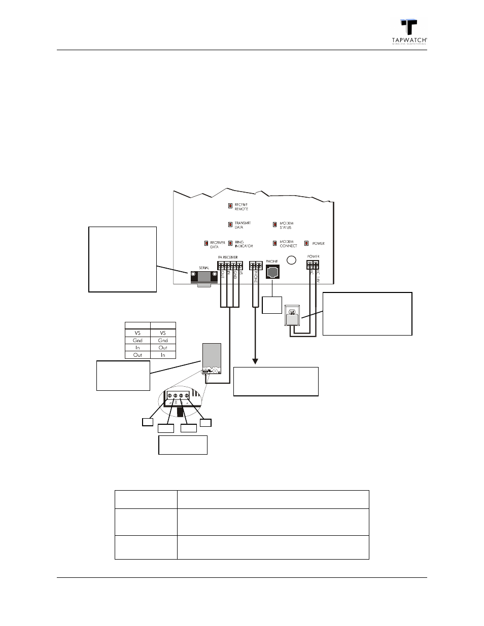
DCC Installation Diagram
Figure 2 DCC Installation Diagram
Table 1: LED Descriptions
Receiver Data
Lit when receiving data from the receiver.
Receive
Remote
Lit when receiving data via the serial connector or modem.
Transmit Data
Lit when transmitting data via the serial connector or
modem.
DCC Receiver
DCC-Receiver
Data Connection
VS
GND
OUT
IN
Receiver Data
Connection
Receiver
Maximum wire
run: 100 ft.
DB9 Serial
Connector
Connects PC to the
DCC. Uses RS232C
cable with DB9
connectors.
Maximum wire run:
25 ft.
RJ11
Jack
Power
Transformer: 120 VAC to 14
VAC
Maximum power wire run:
100 ft.
Phone Line
Note: Tip / ring order does
not matter