En6540 installation instructions – Inovonics DCC5800 User Manual
Page 2
DCC Installation Instructions
2
© 2005 Inovonics Wireless- Document #02962D
4.
Connect the phone line from the screw terminals on a hardwired wall bracket to the terminal
blocks on the DCC.
• The phone line should be connected to the telephone wall outlet using the screw terminals.
The RJ11 plug-in phone connector is provided for easy access to the phone line during
future on-site maintenance.
5.
Use 18 or 20-guage wire to connect 14 VAC power to the DCC with the provided transformer.
• Circuit protection is built into the DCC.
6.
Use the provided screw to secure the transformer to the outlet.
Note:
Telephone and power connections should be as mechanically robust as possible, and protected
from accidental disconnection.
Caution:
Wiring should exit through the back of the DCC, be cut to length, and stapled neatly to the wall
to reduce the possibility of personal injury or equipment damage.
7.
The FA403 requires no additional setup. If you are using an FA403, the installation is
complete. If you are using the EN6540, advance to the next section.
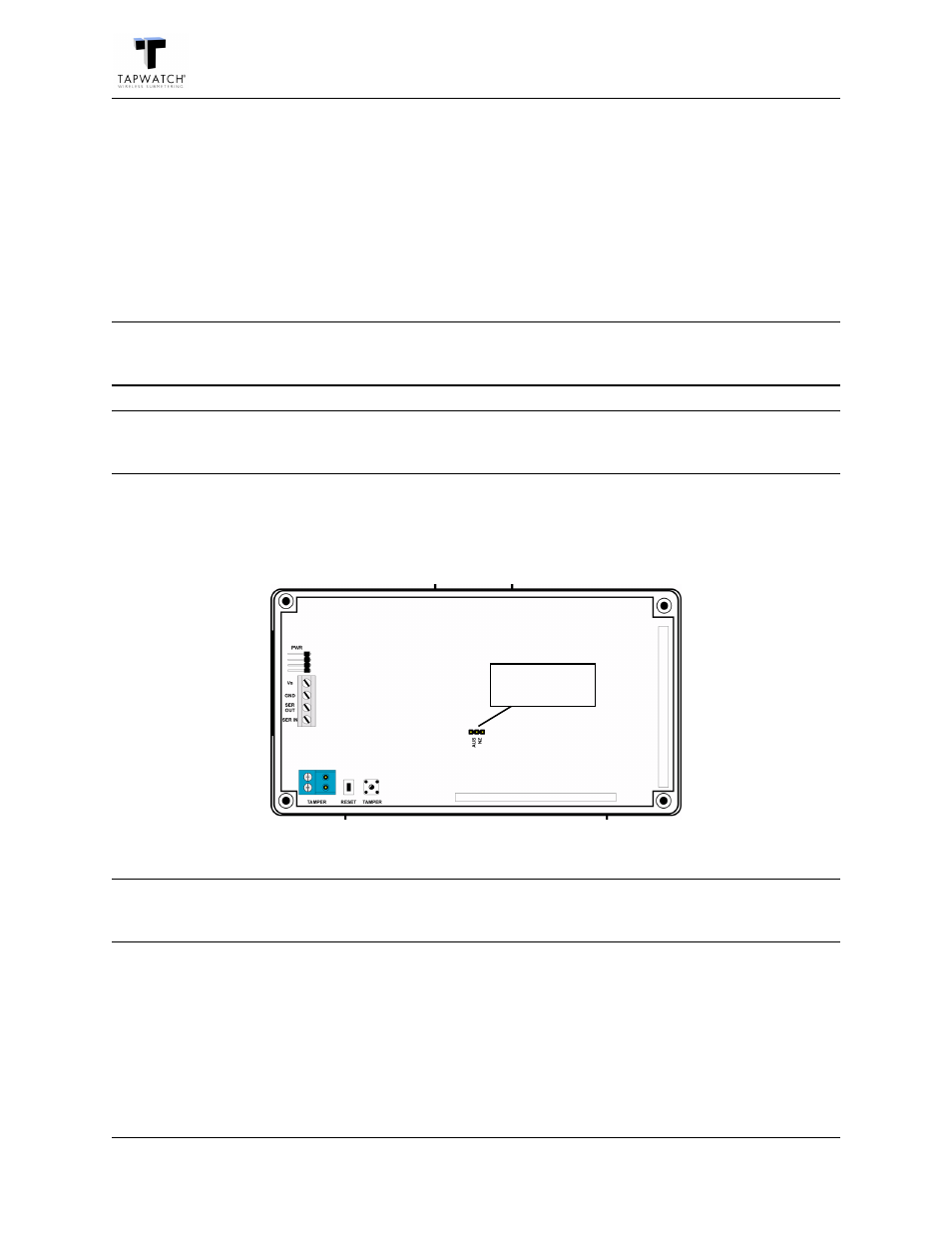
EN6540 Installation Instructions
Figure 1 EN6540 Components
Note:
Connecting an external tamper switch on the EN6540 is not necessary. The external tamper switch
connector is not functional.
Select Frequency Band
EchoStream products are able to use a range of radio frequencies, and must be configured for
your geographic area. If you are using the EN6540 anywhere except North America, you will need
to select the frequency band appropriate to your geographic area. All EchoStream receivers are set
for North America by default. If you are using the EN6540 in North America, there is no need to
select the frequency band.
1.
Use a small screwdriver to press the housing release tab; open the housing.
Frequency band
selection pins