Hardy HI 3010 Filler/Dispenser Controller User Manual
Quick installation guide
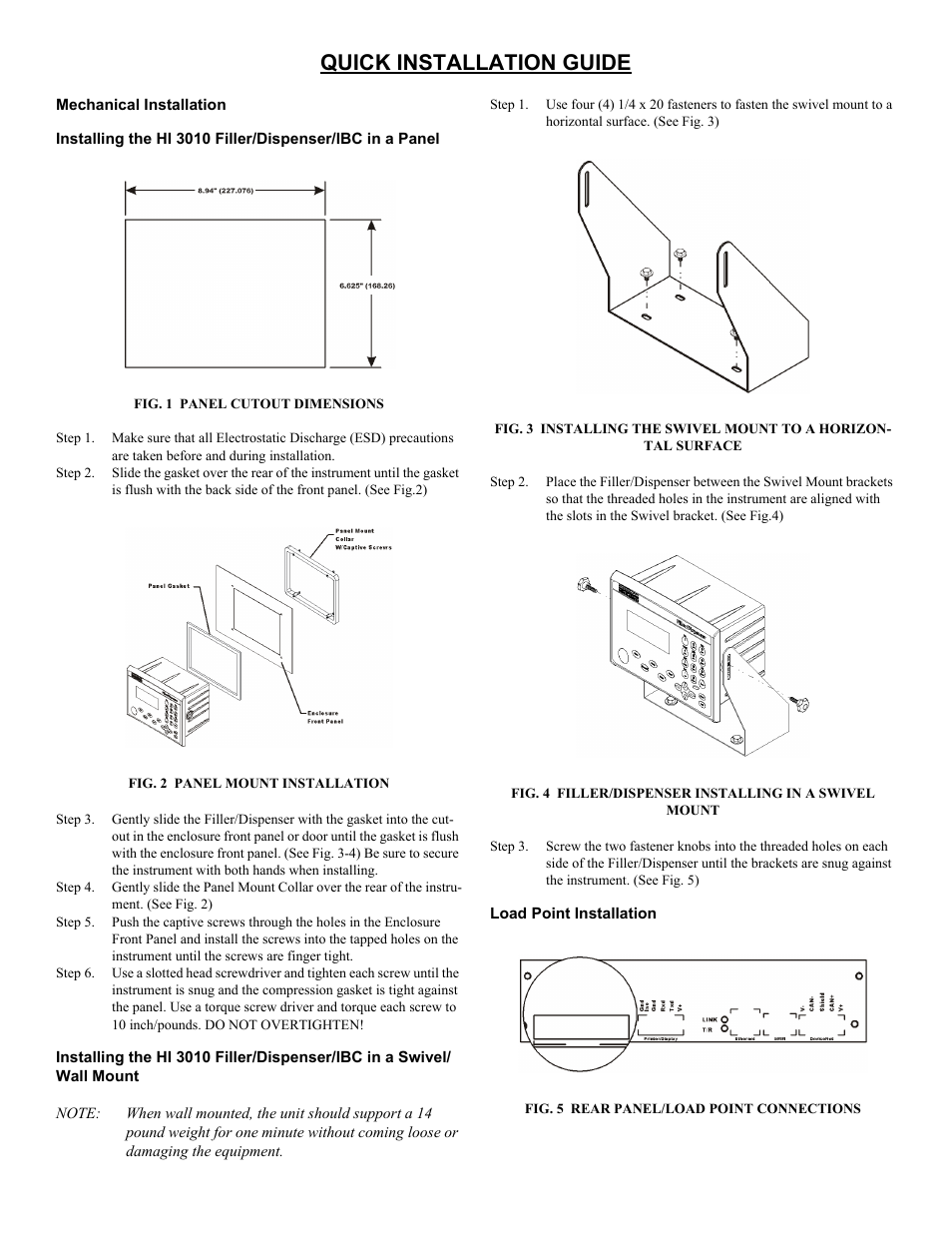
Table of contents
Document Outline
- Quick Installation guide
- Mechanical Installation
- Installing the HI 3010 Filler/Dispenser/IBC in a Panel
- FIG. 1 panel cutout dimensions
- FIG. 2 panel mount installation
- Step 3. Gently slide the Filler/Dispenser with the gasket into the cutout in the enclosure front panel or door until the gasket is flush with the enclosure front panel. (See Fig. 3-4) Be sure to secure the instrument with both hands when installing.
- Step 4. Gently slide the Panel Mount Collar over the rear of the instrument. (See Fig. 2)
- Step 5. Push the captive screws through the holes in the Enclosure Front Panel and install the screws into the tapped holes on the instrument until the screws are finger tight.
- Step 6. Use a slotted head screwdriver and tighten each screw until the instrument is snug and the compression gasket is tight against the panel. Use a torque screw driver and torque each screw to 10 inch/pounds. DO NOT OVERTIGHTEN!
- Installing the HI 3010 Filler/Dispenser/IBC in a Swivel/ Wall Mount
- C2® Load Point Connection
- WARNING: Load cell cable length has been calculated into C2 calibration data. Hardy recommends that you do not cut your Advantage or Advantage Lite load sensor cable, as your C2 accuracy will be affected and the warranty will be voided.
- Step 1. Remove the factory installed jumper from the terminal block if you are connecting an 8 wire cable from the junction box.
- Step 2. Connect the cable (Recommended load cell cable: Hardy Instruments Prt. # 6020-0001) wires to the J9 terminal block according to the cable color chart.
- Step 3. Plug the terminal block into the Channel 1 connector on the rear panel.
- Step 4. For more information concerning C2 Load Point connection, consult the HI 3000 Series Installation and Service Manual.
- Non-C2 Load Point Connection
- Step 1. Remove the factory installed jumper from the terminal block if you have 6 wire load cell cable that includes sense wires from the load cell or junction box.
- Step 2. Connect the cable (Recommended load cell cable: Hardy Prt. # 6020-0001) wires to the Channel 1 terminal block according to the Non-C2 cable color chart, or per manufacturers specification.
- Step 3. Plug the terminal block into the Channel 1 (J9) connector on the rear panel.
- AC Input Power Wiring
- WARNING: do not operate with incorrect line voltage. to do so will result in property damage and/or personal injury. Make sure that the power source does not exceed 240 VAC.
- FIG. 6 power wiring diagram
- FIG. 7 Press enter
- FIG. 8 application selection
- Step 5. Refer to the User Guide, Section 1 of the HI 3010 Filler/Dispenser/IBC for information about Typical Applications.
- Step 6. Press the up or down arrow buttons until the cursor is in front of the application you want.
- Step 7. Press Enter. The application you select will install with default parameters.