7 | accessories – GEA Bock F18 User Manual
Page 22
22
D
GB
F
E
96246-07.2014-DGbRu
WARNING
Several capacity regulators cannot switch at the same time during
compressor operation! Otherwise the sudden change in load can
damage the compressor! Comply with the switching interval of 60 s.
•
Comply with the switching sequence:
Swiching
on LR1 60s LR2 60s LR3
Swiching off
LR3
60s
LR2
60s
LR1
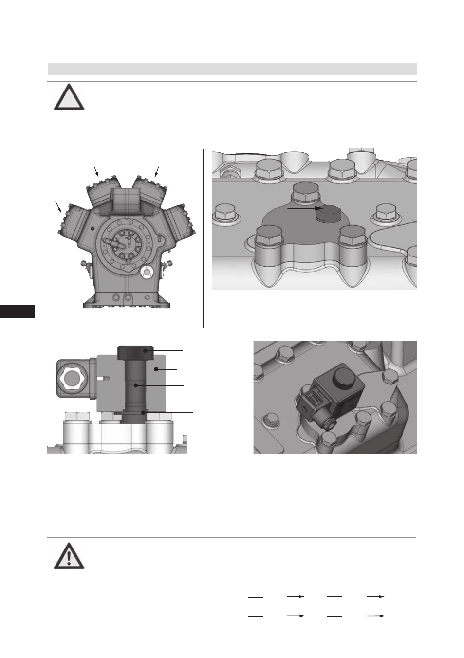
7.1 Capacity regulator
7| Accessories
ATTENTION If the capacity regulator is mounted at the factory, the control com-
ponent (pilot valve) is mounted and connected subsequently by the
customer. If the control component is not connected, the cylinder bank
is switched off permanently. Damage to the compressor is possible!
Delivery status (ex works):
Capacity regulator assembled with cover
(transport protection).
Fig. 22
Fig. 23
LR 3
LR 1
LR 2
Cover
Fig. 24
Screw in control unit (pilot valve) with seal
ring and tight with 30 Nm.
Insert magnetic coil, fasten it with knurled
nut and connect it.
Fig. 25
Before start-up, remove the cover at the capacity
regulator and replace it with the enclosed control
unit (pilot valve).
Caution! The compressor is under pressure!
Depressurize the compressor first.
Control unit
(Pilot valve)
Magnetic coil
Knurled nut
Seal ring