5 | electrical connection, Compressor terminal box, Anschlußkasten verdichter – GEA Bock HGX46 CO2 T User Manual
Page 20: D gb f e, Bock compressors
20
D
GB
F
E
96259-12.2014-DGb
Οnderung
0
Datum
Name
Datum
Bearb.
Gepr.
Norm
1
20.02.2009
Kelich
26.11.2012
Urspr.
2
Ers. f.
3
Ers. d.
4
PW MP10
5
6
7
BOCK COMPRESSORS
8
=
+
9
Bl.
5 D/S MP10 CO2
Bl.
2
1
X SS
Anschlußkasten Verdichter
R1
MP10
Q1
L1
L2
L3
N
PE
F1.1
I=66%
I>
I>
I>
1
2
K1
1
3
4
2
5
6
3
1U1
1V1
1W1
PE
M1
M
Y/YY
2U1
2V1
2W1
F1.2
I=33%
I>
I>
I>
1
2
K2
4
3
4
5
5
6
6
X1 L1 L1 N N 43 43 11
12
14
L
S
M
X2 1 2 3 4 5 6
7
F1.1
F1.2
8
R2
F2
4A
S1
9
10
11
F3
P>
12
13
14
K1
F4
P
15
K1
K1T
16
17
K1T
3.8
18
19
21
L1.1
L2.1
L3.1
L1.2
N
PE
B1
K2
E1
K1
20
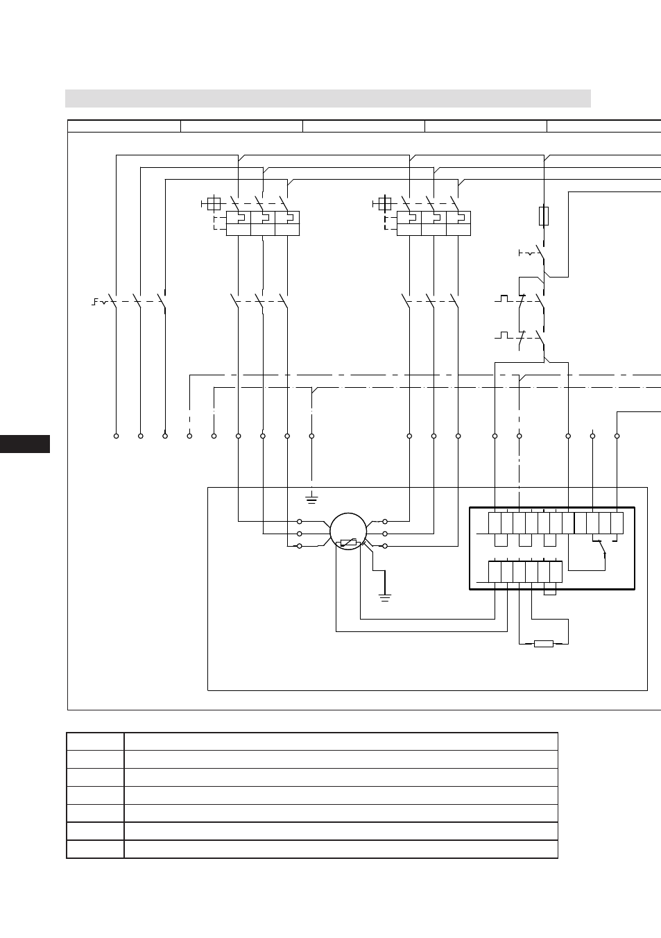
5.3 Basic circuit diagram for part winding start
R1
Cold conductor (PTC sensor) motor winding
R2
Thermal protection thermostat (PTC sensor)
F1.1 / 1.2 2 motor protection switches (66% / 33% of I
A
total)
F2
Control power circuit fuse
F3
High pressure safety monitor
F4
Safety chain (high/low pressure monitoring)
B1
Release switch (thermostat)
Fig. 24
5| Electrical connection
Compressor terminal box