4 | compressor assembly – GEA Bock HGX46 CO2 T User Manual
Page 16
16
D
GB
F
E
96259-12.2014-DGb
Fig. 23
Rigid
fixed point
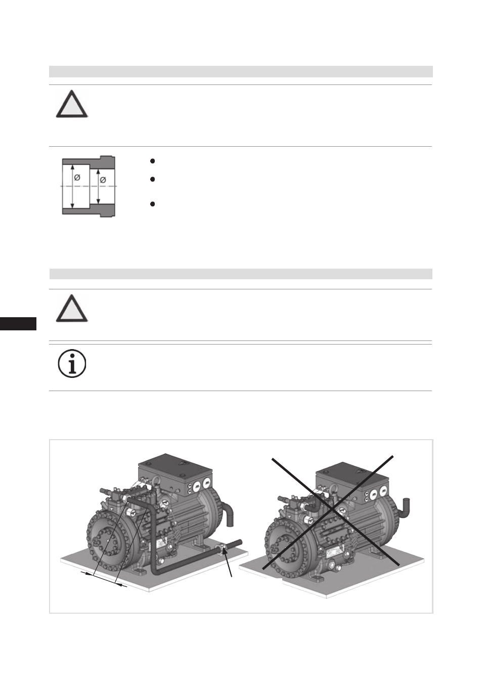
4.10 Laying suction and pressure lines
A rule of thumb:
Always lay the first pipe section starting from the shut-off valve
downwards and
parallel to the drive shaft.
As short as
possible
4| Compressor assembly
ATTENTION Property damage possible.
Improperly installed pipes can cause cracks and tears which can
result in a loss of refrigerant.
INFO
Proper layout of the suction and pressure lines directly after
the compressor is integral to the smooth running and vibration
behaviour of the system.
Material soldering / welding connection: S235 (JRG2C)
The
pipe connections have graduated inside diameters so that pipes with
standart millimetre and inch dimensions can be used.
The connection diameters of the shut-off valves are rated for maximum
compressor output.
The actual required pipe cross section must be
matched to the output. The same applies for non-return valves.
Fig. 22: graduated
internal diameter
4.9 Connecting the pipelines - solder system
ATTENTION Property damage possible.
Remove the valve from the compressor for soldering. Superhea-
ting can damage the valve. Cool the valve body during soldering.
Only solder using inert gas to inhibit oxidation products (scale).