System a - 100, A-179, Controls – Doepfer A-179 Light Controlled CV Source (no longer available) User Manual
Page 3: Doepfer
doepfer
System A - 100
Light Ctr. Volt. Source
A-179
3
3. Controls
1
Light Sensor
Different illumination intensities hitting the built-in light
sensor 1 (photo resistor) result in varying control
voltages at CV outputs " and § .
One can use ”active” illumination (e.g. flashlight, laser
pointer, spotlight) or ”passive” illumination (covering/
shading the sensor from ambient light with hand or
body).
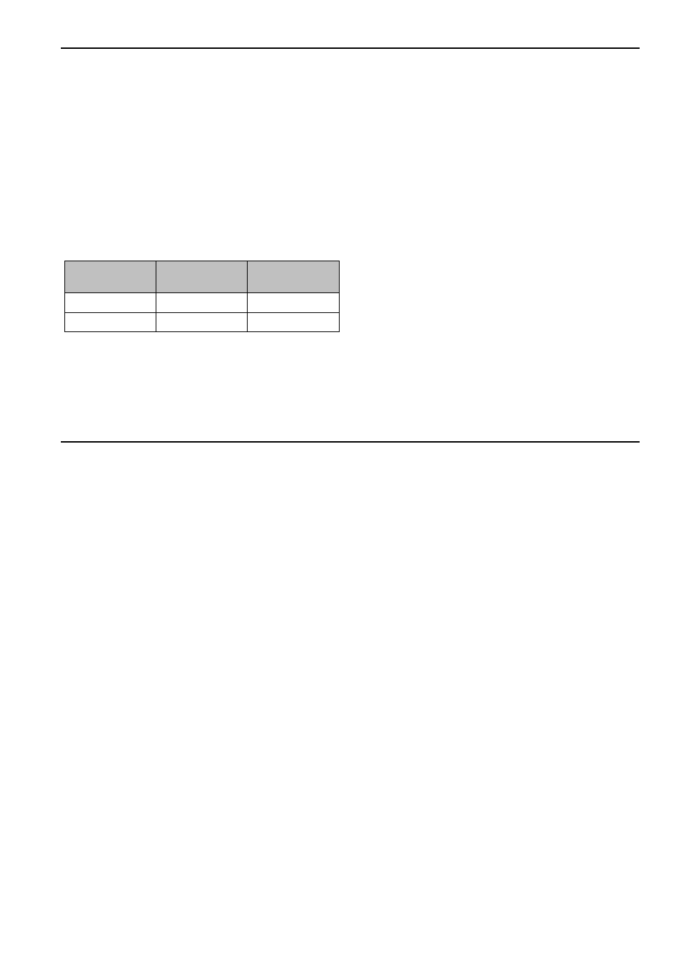
The connection between illumination and control
voltage is as follows:
Instead of the built-in sensor an external photo resistor
may be connected to the normalled jack socket !. In
this case the internal sensor is turned off and the
external sensor is used to control the output voltages.
Any photo resistor (e.g. LDR07) may be used as the
external sensor. If a shielded cable is used the cable
length is largely irrelevant - we tried up to 20m without
problems.
2
Offset
Control 2 is used to adjust the null point, so that the
control voltage at the outputs " and § is about 0 V in
the neutral state. The neutral state depends upon how
the A-179 is being used (e.g. in the ”passive” mode the
neutral state corresponds to having the sensor fully
illuminated and uncovered).
3
LEDs
The LEDs 3 indicate the state of the voltages at CV
outputs " and §.
4
LED
LED 4 shows the presence of a gate signal at gate
output $.
5
Threshold
Using control 5 you set a threshold voltage for the CV
output § , above which a gate signal will be produced
at output $.
Illumination
intensity
Voltage at
CV output §
Voltage at
CV output "
low (dark)
low
high
high (bright)
high
low