A-177, System a - 100, Doepfer – Doepfer A-177 External Foot Controller (no longer available) User Manual
Page 4
A-177
External Foot Controller
System A - 100
doepfer
4
f i g .
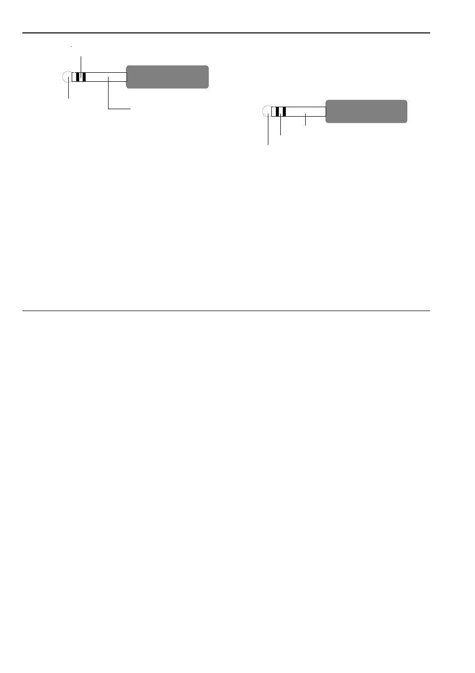
1: foot pedal connection diagram
$
CV 2
CV output $ is the socket for the control voltage CV
2 put out by foot pedal 2. LED 4 shows the level of the
voltage.
&
Gate 1 • / Gate 2
Gate outputs & and / are the sockets for the gate
signals put out by the double foot switch. LEDs 5 and
6
give a visual indication of whether each of the
switches is active.
(
Double Foot Switch
Socket ( is the input for a double footswitch. It is
designed to take a stereo 6.5mm jack plug. The
connection diagram is shown in fig. 2.
fig. 2: connection diagram for the double footswitch
H
The chosen footswitch must be one that
breaks rather than makes the connection.
The
Doepfer
footswitch design fits that
criterion, and also uses the connections
shown in fig. 2.
If you use a foot switch which makes rather
then breaks the connection, it will be neces-
sary to patch in an A-165 Trigger Modifier
module, to invert the signal.
potentiometer
maximum position
potentiometer
slider
potentiometer
minimum position
GND
switch 1
switch 2
- DIY Synth do-it-yourself analog synthesizer (24 pages)
- MKE Universal Midi Keyboard Electronics Kit (17 pages)
- CTM64 Contact to Midi Interface (main board) (20 pages)
- CTM64 Relay Board (8 pages)
- MTC64 Midi to Gate Interface (main board) (16 pages)
- MTC64 Relay Board (8 pages)
- MTC64 Output Board (transistor driver board) (4 pages)
- MTC64 Power Board (8 pages)
- Pocket Electronic (32 pages)
- Dial Electronic (12 pages)
- Wheel Electronic (16 pages)
- USB64 Universal Midi and USB Controller Electronics Kit (20 pages)
- MBP25 Midi Bass Pedal Electronics Kit (16 pages)
- MTV16 Midi-to-Voltage Interface with 16 Analog Voltage Outputs (8 pages)
- A-100 (8 pages)
- A-100AD5 +5V low cost adapter (46 pages)
- A-100(~ 40 MB) (744 pages)
- A-100CGK CV/Gate keyboard (12 pages)
- A-101-1 Vactrol Steiner Filter (6 pages)
- A-101-2 Vactrol Lowpass Gate (6 pages)
- A-101-3 Vactrol Modular Phase Filter (10 pages)
- A-101-9 Universal Vactrol Module (14 pages)
- A-102 Diode Low Pass (6 pages)
- A-104 four-fold Trautonium Formant Filter (6 pages)
- A-105 24dB SSM Low Pass (8 pages)
- A-106-1 Xtreme Lowpass/Highpass Filter (12 pages)
- A-107 Multitype Morphing Filter (18 pages)
- A-108 6/12/24/48 Formant Filter (10 pages)
- A-109 Voltage Controlled Audio Signal Processor (10 pages)
- A-110 Standard VCO (12 pages)
- A-111-1 High End VCO (14 pages)
- A-111-5 Synthesizer Voice (22 pages)
- A-112 Sampler/Wavetable Oscillator (24 pages)
- A-113 Subharmonic Oscillator (14 pages)
- A-114 Dual Ringmodulator (6 pages)
- A-115 Audio Divider (6 pages)
- A-116 VC Waveform Processor (6 pages)
- A-117 Digital Noise / 808 Source (8 pages)
- A-118 Noise/Random (6 pages)
- A-119 External Input/Envelope Follower (8 pages)
- A-120 24dB Low Pass 1 (8 pages)
- A-121 12dB Multimode VCF (10 pages)
- A-123 24dB High Pass (no longer available) (8 pages)
- A-124 Wasp Filter (8 pages)
- A-125 VC Phaser (8 pages)