System a - 100, A-167, Basic principle – Doepfer A-167 Analog Comparator / Offset Generator / Subtractor User Manual
Page 3: Doepfer
doepfer
System A - 100
CMP
A-167
3
3. Basic principle
The module generates internally the voltage U
SUM
:
U
SUM
= a
1
• In
+
- a
2
• In
-
+ Offset
The factors a
1
and a
2
represent the manual attenuators
of the inputs In
+
und In
-
. According to the sign (+/-) of
the resulting voltage U
SUM
the gate output is activated:
U
SUM
> 0 : Gate = "high" (~ +10V)
U
SUM
≤ 0 : Gate = "low" (~ 0V)
The internal voltage U
SUM
is available at the socket §.
Consequently the module can be used to attenuate
and subtract analog voltages and to add a fixed offset
voltage to a voltage (similar to one of the sub-units of
the Attenuator/Offset Generator A-129-3).
The Gap control 4 is used to adjust the so-called
"hysteresis" voltage. As long as this control is set to
zero the switching levels for both on and off state of the
gate signal are identical. As the Gap control is turned
up the switching levels for on and off state fall apart
and a so-called hysteresis appears. In this case after a
state change of the gate output the internal voltage
U
SUM
has to vary at the hysteresis amount before the
gate state will change back.
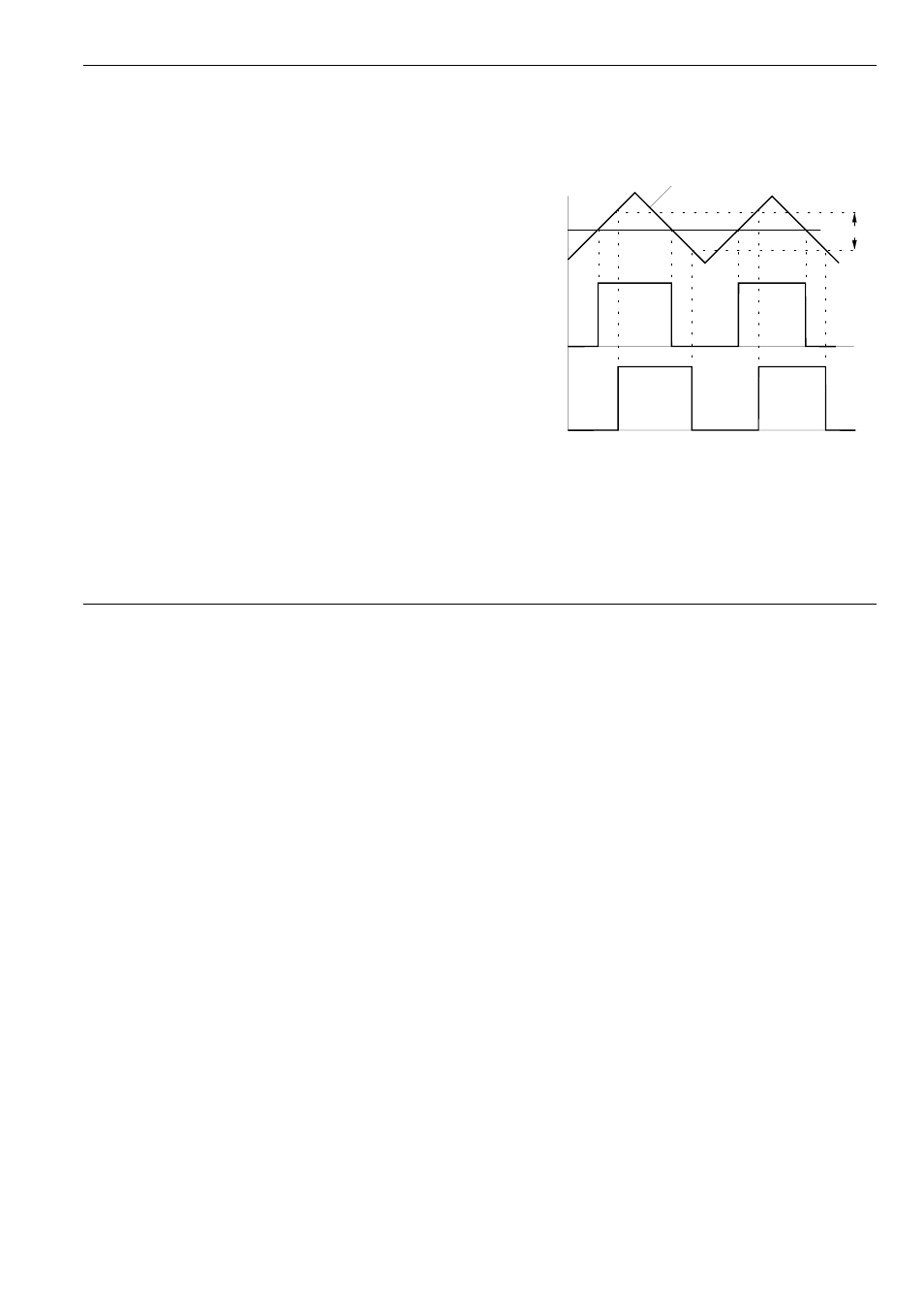
Fig. 1 illustrates the Gap resp. hysteresis function by
means of a triangle LFO input signal.
Fig. 1: Effect of the Gap control on the gate signal
Hysteresis
Input Signal
(LFO Triangle)
Comparator
Output
(gap = 0)
Comparator
Output
(gap > 0)
Comparator
Level