System a - 100, A-150, Doepfer – Doepfer A-150 Dual VC Switch User Manual
Page 5: Dual vcs, Switching between modulation sources, Switching by audio-range signals
doepfer
System A - 100
Dual VCS
A-150
5
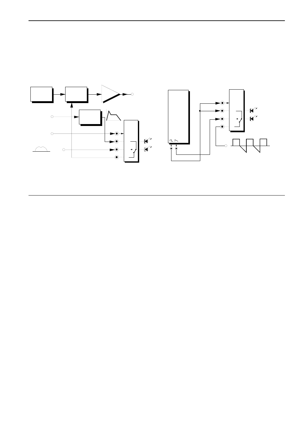
Switching between modulation sources
In the example in Fig. 3, the A-150 switches between
two filter cut-off modulation sources. The control
voltage CV
S
(for instance from a MIDI controller) de-
termines whether the ADSR (when CV
S
= 0 V) or the
output from the mod wheel CV
M
(when CV
S
= +5 V)
controls the cut-off frequency of the filter.
Fig. 3: Switching between modulation sources
Switching by audio-range signals
In Fig. 4, the A-150 is set up to switch the audio output
of a VCO. The switching voltage is provided by the
VCO’s square wave output, with the result that at each
half cycle, synchronised to the VCO frequency, the
waveform changes to sawtooth. Try variations on this
patch, with an independent VCO or LFO providing the
switching voltage, different frequencies, etc..
Fig. 4: Audio-range switching of an audio signal
CV
O/I
A-150
I/O 1
I/O 2
A-110
VCO
VCO
CV
S
VCA
CV
O/I
A-150
I/O 1
I/O 2
VCF
CV
M
ADSR
Gate
- DIY Synth do-it-yourself analog synthesizer (24 pages)
- MKE Universal Midi Keyboard Electronics Kit (17 pages)
- CTM64 Contact to Midi Interface (main board) (20 pages)
- CTM64 Relay Board (8 pages)
- MTC64 Midi to Gate Interface (main board) (16 pages)
- MTC64 Relay Board (8 pages)
- MTC64 Output Board (transistor driver board) (4 pages)
- MTC64 Power Board (8 pages)
- Pocket Electronic (32 pages)
- Dial Electronic (12 pages)
- Wheel Electronic (16 pages)
- USB64 Universal Midi and USB Controller Electronics Kit (20 pages)
- MBP25 Midi Bass Pedal Electronics Kit (16 pages)
- MTV16 Midi-to-Voltage Interface with 16 Analog Voltage Outputs (8 pages)
- A-100 (8 pages)
- A-100AD5 +5V low cost adapter (46 pages)
- A-100(~ 40 MB) (744 pages)
- A-100CGK CV/Gate keyboard (12 pages)
- A-101-1 Vactrol Steiner Filter (6 pages)
- A-101-2 Vactrol Lowpass Gate (6 pages)
- A-101-3 Vactrol Modular Phase Filter (10 pages)
- A-101-9 Universal Vactrol Module (14 pages)
- A-102 Diode Low Pass (6 pages)
- A-104 four-fold Trautonium Formant Filter (6 pages)
- A-105 24dB SSM Low Pass (8 pages)
- A-106-1 Xtreme Lowpass/Highpass Filter (12 pages)
- A-107 Multitype Morphing Filter (18 pages)
- A-108 6/12/24/48 Formant Filter (10 pages)
- A-109 Voltage Controlled Audio Signal Processor (10 pages)
- A-110 Standard VCO (12 pages)
- A-111-1 High End VCO (14 pages)
- A-111-5 Synthesizer Voice (22 pages)
- A-112 Sampler/Wavetable Oscillator (24 pages)
- A-113 Subharmonic Oscillator (14 pages)
- A-114 Dual Ringmodulator (6 pages)
- A-115 Audio Divider (6 pages)
- A-116 VC Waveform Processor (6 pages)
- A-117 Digital Noise / 808 Source (8 pages)
- A-118 Noise/Random (6 pages)
- A-119 External Input/Envelope Follower (8 pages)
- A-120 24dB Low Pass 1 (8 pages)
- A-121 12dB Multimode VCF (10 pages)
- A-123 24dB High Pass (no longer available) (8 pages)
- A-124 Wasp Filter (8 pages)
- A-125 VC Phaser (8 pages)