System a - 100, A-148, Indicators – Doepfer A-148 Dual Sample&Hold User Manual
Page 3: Doepfer
doepfer
System A - 100
Dual S&H
A-148
3
3. Indicators
1
LEDs
These LEDs give a visual indication of the voltage
level of the sampled and held signal (- LED: negative
voltages, + LED: positive voltages).
4. In / Outputs
!
Trig In
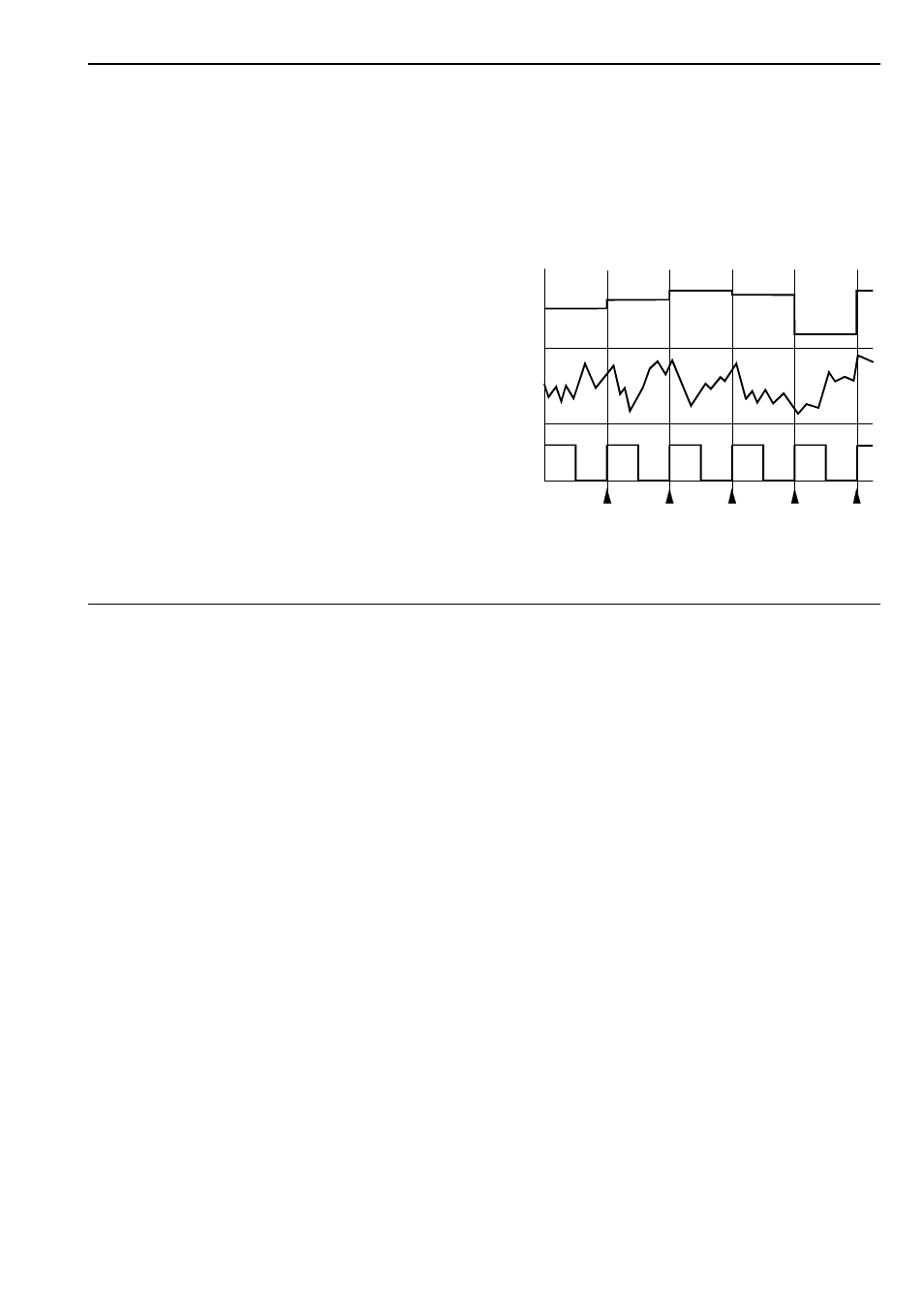
The trigger input signal decides the rate at which the
sampling takes place. Triggering takes place at the
leading edge of the waveform (see arrows in Fig. 1),
so the width of the pulse isn’t important.
"
Smp. In
Socket " is the sample input, where the signal to be
sampled is patched in. For the old version
(manufactured until August 2005) the signal fed into
this socket has to be in the range -8V...+8V. For
voltages beyond this range the S&H function will not
work any longer. But the module cannot be destroyed
as long as the voltage is in the range -12V...+12V. And
that is the maximum voltage output from any A-100
module. Consequently within the A-100 no damage is
possible.
For the new version of the module manufactured from
August 2005 the complete A-100 voltage range can be
processed (i.e. -12...+12V).
§
S&H Out
The ‘sampled and held’ voltage is available at the S&H
output (see Fig. 1).
Fig. 1: S&H module signal diagram
Trig.
In
Smp.
In
S&H
Out