System a - 100, A-144, Controls – Doepfer A-144 Morphing Controller User Manual
Page 3: Doepfer, Morphing controller, 2man. morph
doepfer
System A - 100
Morphing Controller
A-144
3
3. Controls
1
CV
Use attenuator 1 to adjust the level of the control
voltage at CV input ! affecting the morphing effect.
2
Man. Morph.
Control 2 adjusts the manual morphing.
The module generates an internal control voltage that
is the sum of the voltage generated by the manual
control 2 and the external control ! attenuated with
the attenator 1. This internal control voltage is fed to
the 4 internal control voltage modifiers that generate
the 4 morphing control voltages appearing at the out-
puts " to $.
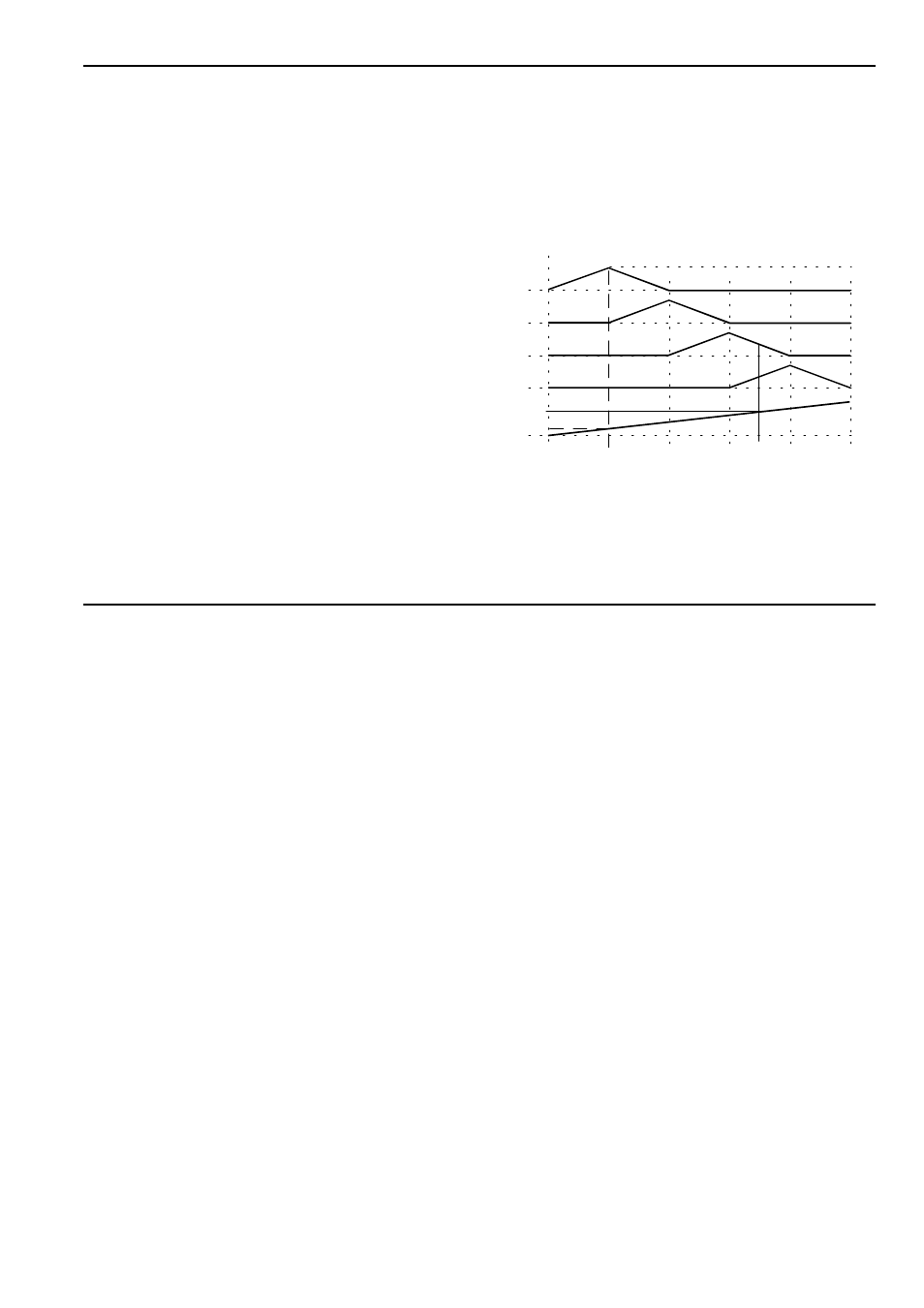
Fig. 1 shows the connection between internal control
voltage and the 4 output control voltages. The internal
voltage is equivalent to the position of control 2 if no
external CV is used, or is equivalent to the external
control voltage ! if manual control 2 is set to 0 and
attenator 1 is turned fully clockwise.
E.g. the control voltage “a” has the following effect:
Out 1 = max. (i.e. +5V) • Out 2 = 0 • Out 3 = 0 • Out
4 = 0.
In case “b” the following output voltages appear:
Out 1 = 0 • Out 2 = 0 • Out 3 = 50 % (i.e. +2.5V) • Out
4 = 50 % (i.e. +2.5V).
Fig. 1:
Connection between internal control voltage
(= sum of manual CV and external, attenua-
ted CV) and the resulting output control vol-
tages (range of input and output voltages is
0...+5V)
CV Out 1
CV Out 2
CV Out 3
CV Out 4
CV In
a
b
0 V
+5 V