System a - 100, A-133, Controls and indicators – Doepfer A-133 Dual Polarizer User Manual
Page 3: Doepfer
doepfer
System A - 100
Dual VC Polarizer
A-133
3
3. Controls and Indicators
1
LEDs
The two LEDs indicate the amplification of the pola-
rizer in question (attention: in contrast to the LED
displays of other modules they do not show the signal
but the amplification factor !).
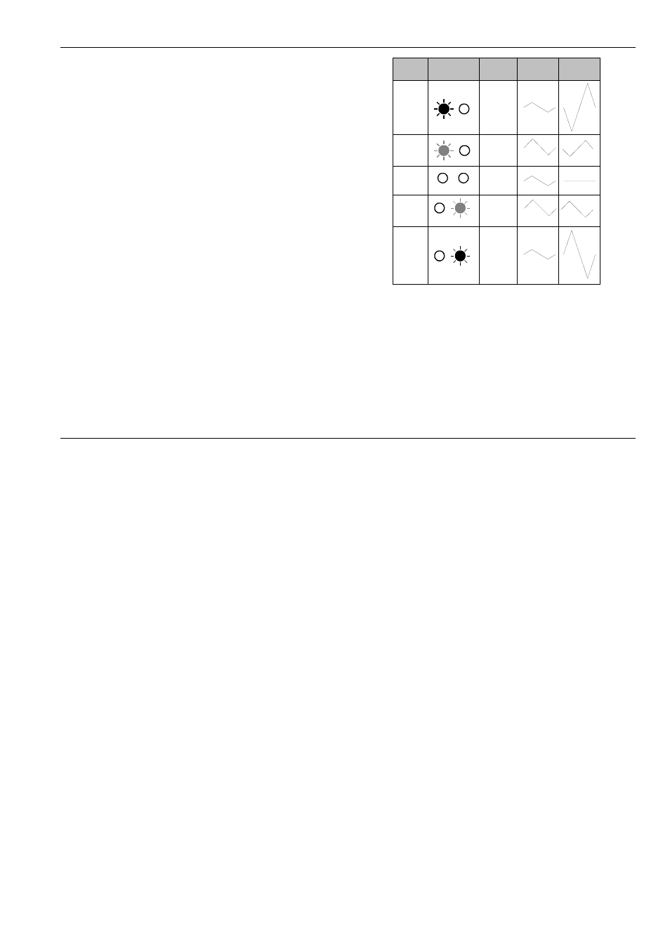
Tab. 1 shows the connection between LED display
and amplification. At maximum negative amplification
(about -2.5, signal inverted !) the left LED lights with
maximum brightness. At maximum positive amplifica-
tion (about +2.5, signal not inverted!) the right LED
lights with maximum brightness. With amplification
about zero (i.e. no output signal) both LEDs are off.
2
CV
The attenuator 2 is used to adjust the effect of the
external control voltage on the amplification.
3
Man.
This control is used to adjust the amplification manu-
ally. The range is about -2.5 to +2.5 (without external
control voltage). The middle position corresponds to
about zero amplification (but in any case the LEDs
should be used to find out the current amplification).
Tab. 1: Connection between manual control (Man.) ,
LED display, amplification (a) and effect on
the output signal
H
It is possible to obtain other amplification
ranges (e.g. -1 ...+1 or -5 ...+5). For this a
resistor has to be replaced. Please look at
the A-100 service manual or contact hard-
[email protected]. We think that -2.5...+2.5
is a good compromise as higher amplificati-
Man.
LEDs
a
In
Out
-5
-2,5
-2
-1
0
0
2
1
5
2.5