A-124, System a - 100, Controls – Doepfer A-124 Wasp Filter User Manual
Page 4: Doepfer
A-124
Wasp Filter (VCF 5)
System A - 100
doepfer
4
4. Controls
1
Lev.
This attenuator controls the input level of the signal to
be filtered, entering the module at input ! .
H
If the filter’s output signal is distorted, turn
this control down, unless the distortion is
wanted as a special effect.
2
Freq.
The filter frequency is adjusted with this control.
3
CV 2
If you want to control or modulate the cut-off frequency
by a voltage patched into input §, use attenuator 3
CV 2 to set the level of voltage control.
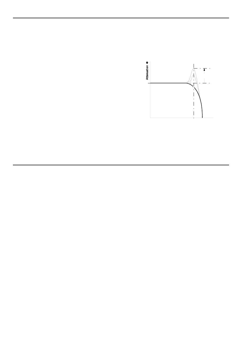
4
Res.
With this control you adjust the resonance of the filter
(also known as emphasis or Q), which emphasises
the frequencies around the cut-off frequency f
C
. As the
value for Q gets higher, the frequencies around the
cut-off frequency f
C
are emphasised. Fig. 2 shows this
process using a low-pass filter as an example (a
high-pass filter would produce a mirror-image). This
way, you can make the frequencies around the cut-off
point stand out more.
In band-pass mode, an increase in Q’s value makes
the bandwidth narrower. The same is true of notch
mode, but of course in this case this narrower band will
be rejected, instead of let through.
Fig. 2:
How resonance affects the response of a
low-pass filter around the cut-off frequency.
fc
Resonance Q
Frequency ➨
➨
➨
➨
0 db