System a - 100, A-110, Doepfer – Doepfer A-110 Standard VCO User Manual
Page 7: Sync, Cv 1 • § cv 2
doepfer
System A - 100
VCO
A-110
7
5. In / Outputs
!
SYNC
Socket ! is the Sync Input for the VCO. What sync
means in this context is that the waveform of one VCO
("Slave") is locked to the waveform of another VCO
("Master"), by connecting the audio out of the master
VCO to the Sync input of the slave VCO.
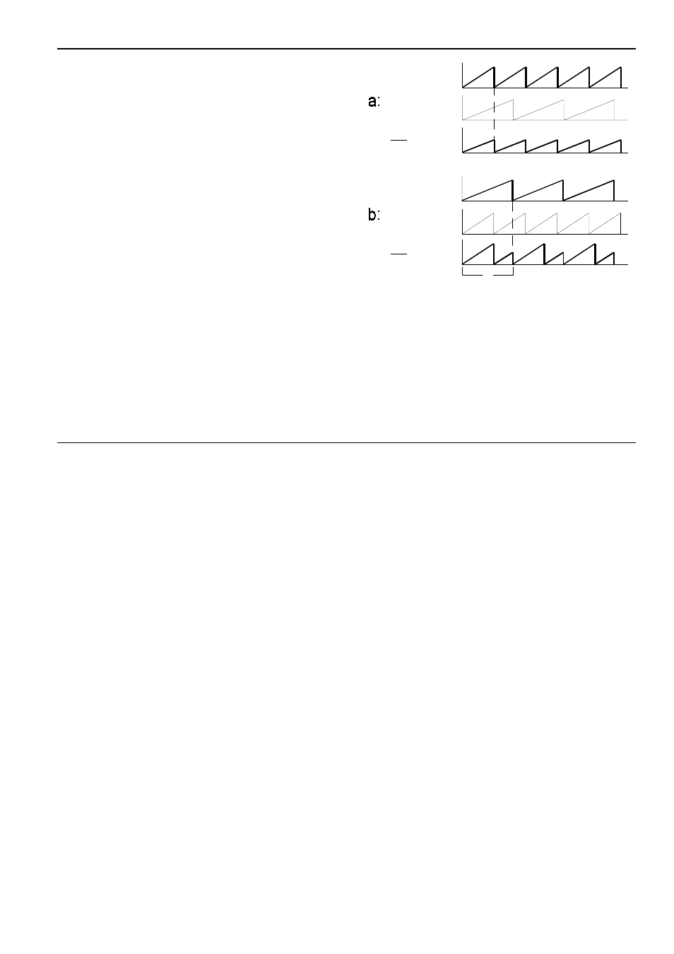
In the A-110, this is designed as "Hard Sync". Check
out the following example (see Fig. 7): the slave
VCO’s sawtooth waveform is always reset to the begin-
ning of a cycle whenever the master VCO’s sawtooth
waveform starts a new cycle. If f
M
- the frequency of
the master VCO - is higher than f
S
(the slave’s fre-
quency), then the slave’s pitch is synced exactly to the
master’s (Fig. 7a).
In the opposite situation, where the master VCO’s pitch
is lower than the slave (f
M
< f
S
), the master again
imposes its frequency on the slave (Fig. 7 b: cycle T
exactly matches the master VCO’s cycle). But at the
same time, harmonic sidebands are produced by the
slave VCO’s changed waveform, which can create
interesting timbral effects.
Fig. 7: Hard Sync on the A-110
"
CV 1 • § CV 2
Sockets " and § are CV inputs for controlling the
VCO’s frequency (pitch). The voltages at these inputs
are summed. The inputs follow the 1V / octave rule
exactly.
Master
Slave
Slave with Hard Sync
T
f < f
M
S
Master
Slave
Slave with Hard Sync
f > f
M
S