Doepfer USB64 Universal Midi and USB Controller Electronics Kit User Manual
Page 8
Page 8
User's Guide V1.3
USB64
USB connector (4)
If the data generated by USB64 has to be transmitted via USB the socket (4) is connected to
the USB socket of the receiver (normally that's a computer with USB interface). The operating
system of the computer has to support the so-called generic USB device class driver for Midi
devices. This driver is supported by Windows XP (SP2 recommended), Vista and Mac OSX
operating systems. Consequently older Windows or Mac operating systems that do not include
this driver cannot be used. In this case the Midi output of the USB64 has to be used.
Provided that the operating system does support the generic USB Midi device class driver the
USB64 is recognized by the computer as soon as USB64 is connected to the computer. Then
the corresponding driver is activated and normally an acoustic notification is made. This maybe
complemented by information bubbles in the task bar (e.g. Windows XP). After that a new Midi
in/output named USB audio device is available in the corresponding programs. If another
message appears (e.g. USB device not recognized) the required driver is not available or
damaged or does not work for other reasons. As this behaviour depends upon the computer
and the operating system we cannot give any support as the reasons can be manifold and do
not depend upon the USB64 but the computer and the operating system installed on the
computer.
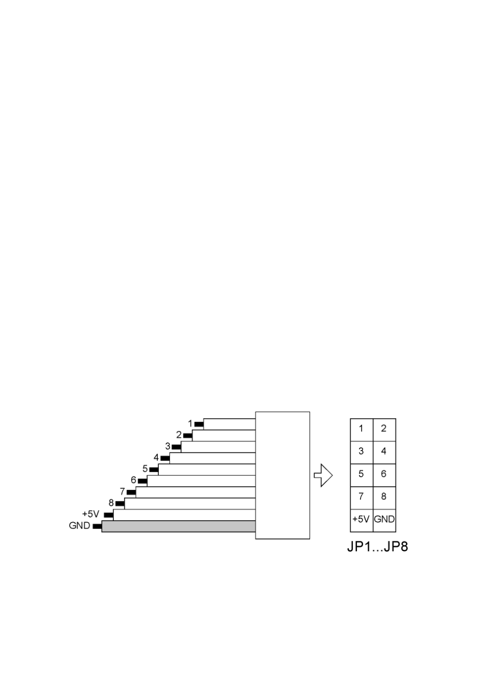
Connectors for the 64 controls (5)
The eight pin headers JP1 – JP8 are used to connect the 64 controls. All pin headers have
available these signals: GND, +5V and 8 control voltage inputs (range 0...+5V).
Remark: In the following the terms GND (= abbreviation of ground) and 0V (zero volts) are used
synonymous.
The control voltages are normally generated by rotary or fader potentiometers that are
connected between GND and +5V. In this case the wiper of the potentiometers outputs a
voltage in the range 0...+5V while the potentiometer is operated. Another possibility is the
connection of momentary switches or toggle switches.
The above sketch shows the pinout of each pin header JP1 – JP8. The orientation is the same
as in the picture on the previous page. The pins labelled 1 ... 8 are the eight control voltage
inputs of the corresponding pin header. The upper pin header (JP1) is assigned to the inputs
1...8, the second (JP2) to 9...16 and so on until JP8. This is assigned to the inputs 57...64.