Doepfer USB64 Universal Midi and USB Controller Electronics Kit User Manual
Page 15
USB64
User's Guide V1.3
Page 15
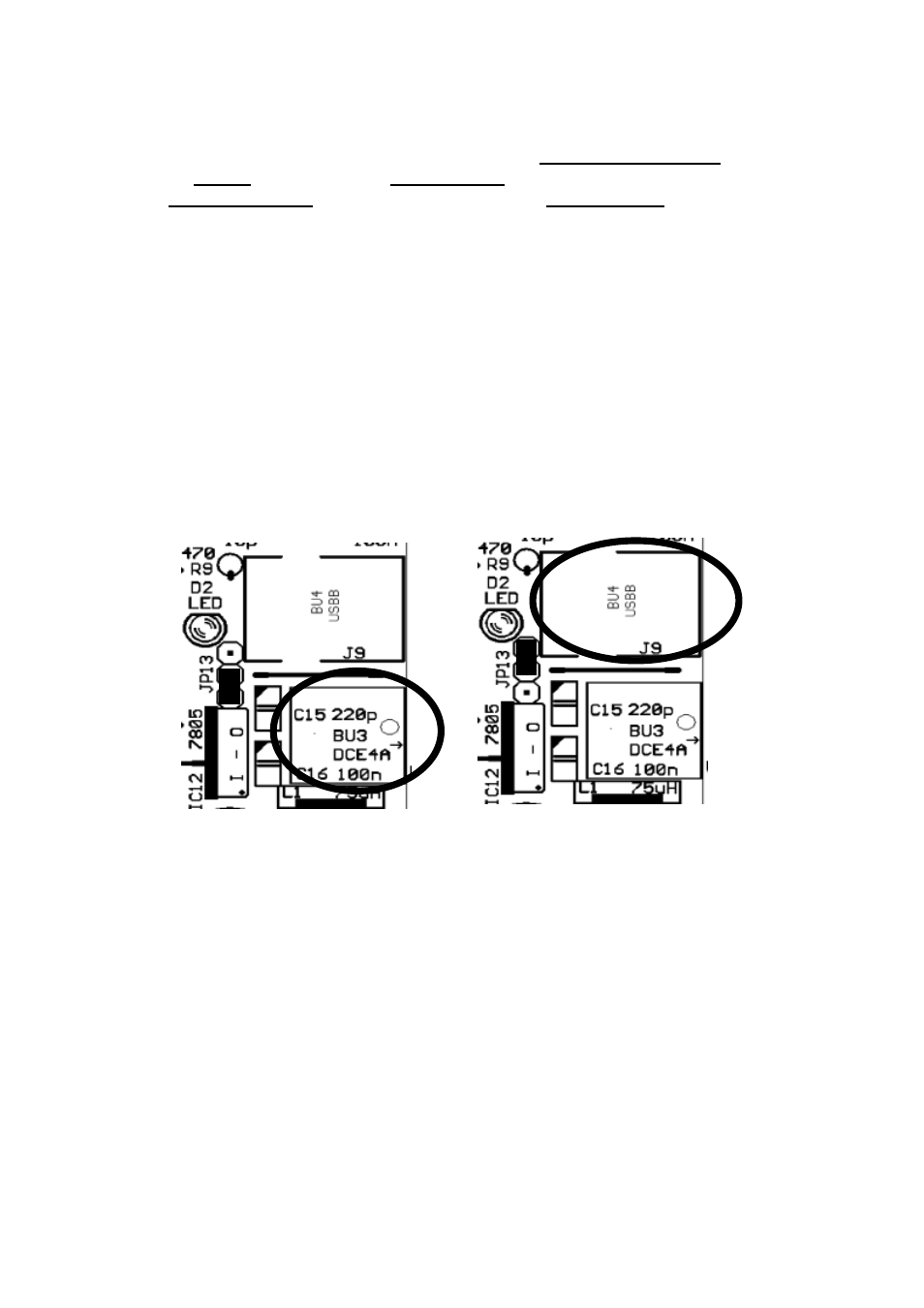
(8) Pin header JP13
JP13 was used to choose the type of power supply. If an external power supply was used to run
the USB64 the jumper had to be in the lower position (towards the voltage regulator 7805). If
USB64 was powered via USB the jumper had to be in the upper position (towards the LED) and
the external power supply had to be removed. This was the situation till version V1.2.
Now in V1.3 this is made automatic by two diodes BAT42, which are assembled instead of
JP13 and the jumpers.
But in some situations it could be necessary to choose the type of power supply manually
again.
F.e. if your potentiometers and/or switches that are connected need more power your USB port
can offer ( USB64 itsself need 30 mA). Than you maybe want to use the external power supply
interface from USB64 together with USB connected to your computer.
So you had te reassemble the old JP13 situation by removing the diodes and reassemble JP13
/ wire this direct on the board at the position of former JP13.
But you also can use an external powered USB Hub between your computer and USB64, if you
need more power that the USB port on your computer can supply.
(9) Control LED
The LED flashes for about 2 seconds after power on and then stays lit. If this does not happen
f.e. the external power supply connected to BU3 could be defective.
As soon as Midi messages are generated by the USB64 the LED flashes to indicate the Midi
out activity of USB64. Consequently the LED can be used to check the fundamental function of
USB64.
In addition the LED displays each change of the jumper settings of JP9.
supply via external wall
outlet power supply
supply via USB