4 cv/gate connection – Doepfer Regelwerk (device no longer available) User Manual
Page 13
Doepfer Musikelektronik GmbH
User manual V1.0
REGELWERK V1.2
✵
✶
✷
✸
so the
REGELWERK
will be the master.
The
REGELWERK
can also be set to receive
•
a SYNC signal at this socket (which is now
functioning as an input). In this case, the
other equipment has to be set to send SYNC
pulses.
•
The SYNC signal is simply a bog-standard
square wave, with a range from 0 to 5V.
That means that a normal LFO from an
analogue synth module can be used as a clock
source. That way, it's possible to relax the tight
tempo of the
REGELWERK
SYNC signal and
produce a syncopated groove.
−
Note that in connecting the SYNC socket on
the
REGELWERK
with another piece of
equipment, nothing will happen if both units
are set to input or both to output.
6.4 CV/Gate connection
•
In the current software version, the 16 mini-
jack sockets on the rear of the
REGELWERK
are designed purely for sequencer work
−
8 x CV for pitch control
−
8 x Gate
⇒
The CV/Gate option runs simultaneously and
parallel to the MIDI output. Both can function
at the same time. In effect it is doubling the
number of voices that the
REGELWERK
can
control, with the proviso that the CVs put out
convey exactly the same information as the
MIDI pitch and note-on/off data.
•
The eight CV outputs are dedicated to
sequencer note information, with output 1
responding to track 1, output 2 to track 2, and
so on up to output 8 responding to track 8.
The respective CVs cover a range from 0 to
approximately 5
V.
−
The response of the CVs is designed to be
exactly one volt to the octave, so that they're
ideal for pitch control.
−
The relationship between note numbers and
voltage output is:- note number 36 = 0 Volts;
note number 100 = 5 Volts.
−
Notes outside of this range – either below
(note numbers 0-35) or above (note numbers
101 - 127) are folded back to the bottom and
top octaves respectively., and so overlap the
response to note numbers 36-100.
•
The eight GATE outputs put out their
respective gate signals whenever there is an
event programmed at the particular step
position on their track.
−
For Gate Off, the level drops to 0 Volts, and
for Gate On rises to 5 Volts.
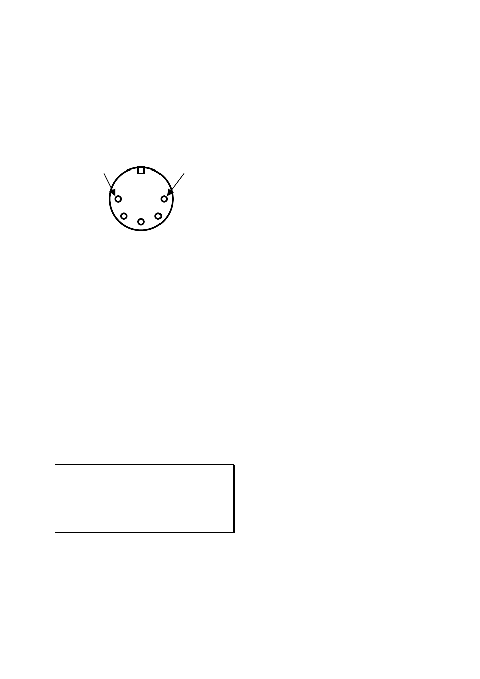
Pin 3:
Clock signal
0-5 Volts
Pin 1
Start (+5 Volts)
Stop (0Volts)