Connections, Functions of the led – Doepfer Pocket Control/Pocket Fader (device no longer available) User Manual
Page 4
pocketControl
Owners Manual
pocketControl
Owners Manual
Page 4
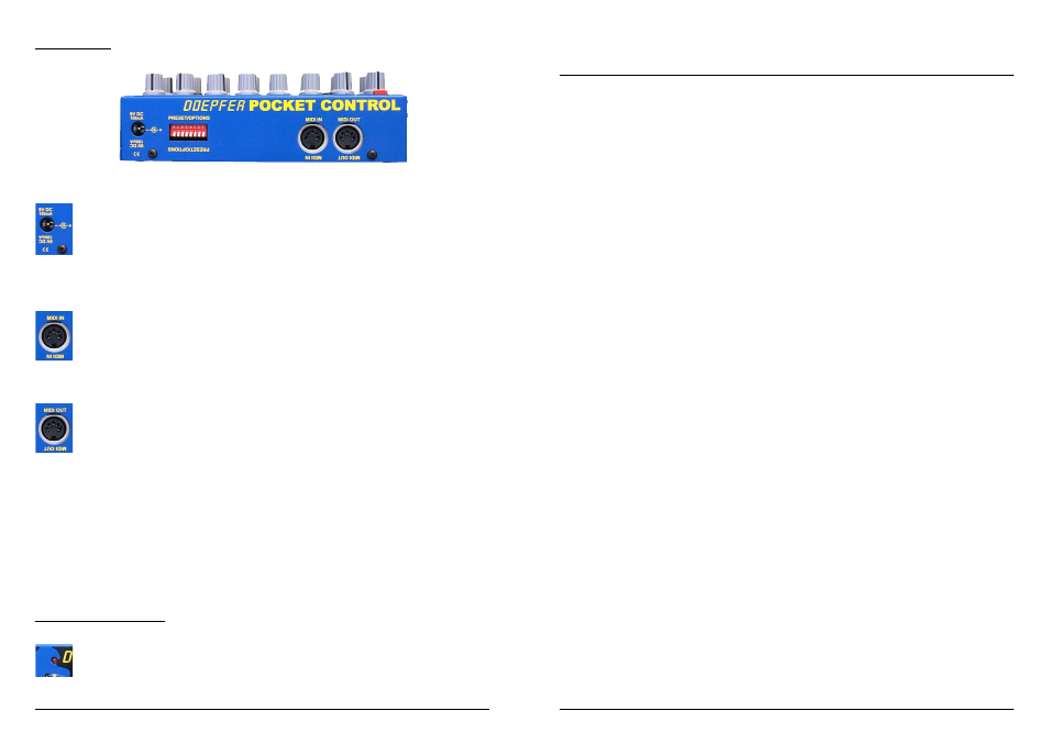
Connections
The pocketC does not have a built in power supply (not enough room left inside!),
but uses an external adaptor which can be from 7v to 12v and at least 100mA. The
connection polarity is positive inner. Although the pocketC has a built in protection
diode for protection against incorrect polarity, the pocketC can still be damaged by
using an incorrect adaptor, so only use an approved adaptor and avoid using multi-
polarity type adaptors with voltage level and polarity switching, as inadvertant settings
can cause problems.
Connect the MIDI out of the controlling keyboard to the MIDI IN of the
pocketC. The MIDI input also allows control of the pocketC, such as with program
changes to select presets, and to receive it’s own Sys-Ex messages for setting up the
128 preset memories (held in non-volatile memory).
Connect the MIDI OUT of the pocketC to the sequencer (computer) or sound
generator MIDI in. The pocketC merges the incoming data with it’s own data, so the
MIDI OUT is a data merge of MIDI in and data generated by the pocketC. There is
no use for a separate MIDI thru with this type of device. Note that if extremely large
Sys-Ex dumps are passed through the pocketC then it is advisable not to move any
pocketC knobs whilst this transmission is taking place, as the merge abilities of the
pocketC were not intended to work whilst this kind of intense transmission is taking
place.
If multiple pocketC’s are being used then the MIDI connections can be chained
together so that all the pocketC’s produce one composite data from the last MIDI out in the
chain.
Functions of the LED
The LED indicates the status of the pocketC in various modes. For example,
under normal operation the LED indicates MIDI input activity, and also MIDI out
activity when moving the control knobs on the pocketC. The LED also indicates:-
Page 21
Parameter 2: Event Definition
Decimal
Hex
Definition
0
00
Controller
1
01
Pitch Bend
2
02
Mono Aftertouch
3
03
Program Change
4
04
Poly Aftertouch
5
05
Note On
6
06
Note Off
7
07
free
8
08
RPN0 MSB
9
09
RPN0 LSB
10
0A
RPN1 MSB
11
0B
RPN1 MSB
12
0C
free
13
0D
free
14
0E
RPN127 MSB
15
0F
RPN127 LSB
16
10
NRPN0 MSB
17
11
NRPN0 LSB
18
12
NRPN1 MSB
[XG Multi / GS]
19
13
NRPN1 LSB
[XG Multi / GS]
20
14
NRPN8 MSB
21
15
NRPN8 LSB
22
16
NRPN9 MSB
23
17
NRPN9 LSB
24
18
NRPN10 MSB
25
19
NRPN10 LSB
26
1A
NRPN20 MSB
[XG Drum Instrument Cutoff ]
27
1B
NRPN20 LSB
[XG Drum Instruemnt Cutoff ]
28
1C
NRPN21 MSB
[XG Drum Instrument Resonance]
29
1D
NRPN21 LSB
[XG Drum Instrument Resonance]
30
1E
NRPN22 MSB
[XG Drum Instrument EG Attack]
31
1F
NRPN22 LSB
[XG Drum Instrument EG Attack]
32
20
NRPN23 MSB
[XG Drum Instrument EG Decay]
33
21
NRPN23 LSB
[XG Drum Instrument EG Decay]
34
22
NRPN24 MSB
[XG/GS Drum Instrument Pitch Coarse]
35
23
NRPN24 LSB
[XG/GS Drum Instrument Pitch Coarse]
36
24
NRPN25 MSB
[XG Drum Instrument Pitch Fine]
37
25
NRPN25 LSB
[XG Drum Instrument Pitch Fine]
38
26
NRPN26 MSB
[XG/GS Drum Instrument Level]
39
27
NRPN26 LSB
[XG/GS Drum Instrument Level]
40
28
NRPN28 MSB
[XG/GS Drum Instrument Pan]
41
29
NRPN28 LSB
[XG/GS Drum Instrument Pan]
42
2A
NRPN29 MSB
[XG/GS Drum Instrument Reverb Send]
43
2B
NRPN29 LSB
[XG/GS Drum Instrument Reverb Send]
44
2C
NRPN30 MSB
[XG/GS Drum Instrument Chorus Send]
45
2D
NRPN30 LSB
[XG/GS Drum Instrument Chorus Send]
46
2E
NRPN31 MSB
[XG/GS Drum Instrument Variation Send]
47
2F
NRPN31 LSB
[XG/GS Drum Instrument Variation Send]
48
30
NRPN32 MSB
49
31
NRPN32 LSB
50
32
NRPN33 MSB
51
33
NRPN33 LSB
52
34
NRPN99 MSB
53
35
NRPN99 LSB
54
36
NRPN100 MSB
55
37
NRPN100 LSB