Cub Cadet 8000 Series User Manual
Page 9
5
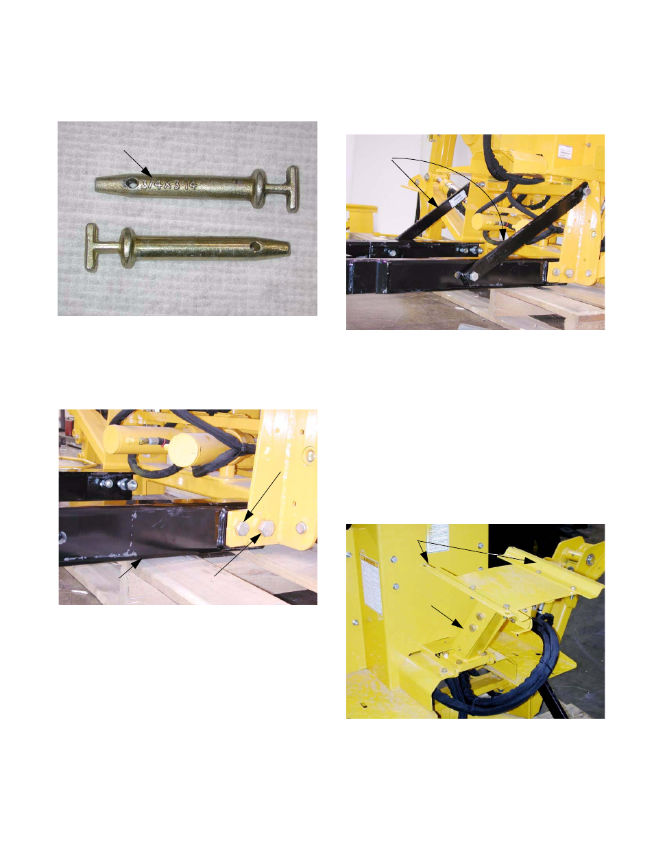
1.28. If necessary, the numbers may be ground off of
the T handle clevis pins to ease installation.
See Figure 1.28.
1.29. After correct fit is confirmed bet ween the mount-
ing frame, receiver, and latching bracket, attach
the mounting frame to the backhoe.
See Figure 1.29.
NOTE: The guide tabs at the front of the mount-
ing frame face up.
1.30. Secure the mounting frame to the backhoe using
the two 7/8” X 3 1/2” bolts, nuts, and lock wash-
ers in the rear holes, and the 3/4” X 3 1/2” bolts,
nuts and lock washers in the front holes.
Figure 1.28
T handle clevis pin
with embossed numbers
May need to remove numbers
Figure 1.29
7/8” bolt
3/4” bolt
Mounting frame
1.31. Install the braces diagonally between the mount-
ing frame and the backhoe, using four 3/4” X 2 1/
2” bolts, nuts, and lock washers.
See Figure 1.31.
NOTE: There is a slight off-set to the braces,
allowing them to fit flush against the backhoe
and mounting frame.
1.32. Verify that the mounting frame and backhoe are
at a 90 degree angle to one another, then tighten
the 7/8” bolts using a pair of 1 5/16” wrenches.
Tighten the 3/4” bolts using pair of 1 1/8”
wrenches.
1.33. Mount the seat pedestal to the backhoe. Tighten
the bolts using a pair of 17mm wrenches.
See Figure 1.33.
1.34. Position the backhoe behind the tractor, oriented
as it is to be installed.
Figure 1.31
Braces
Figure 1.33
Seat pedestal
Seat brackets