Cub Cadet 8000 Series User Manual
Page 7
3
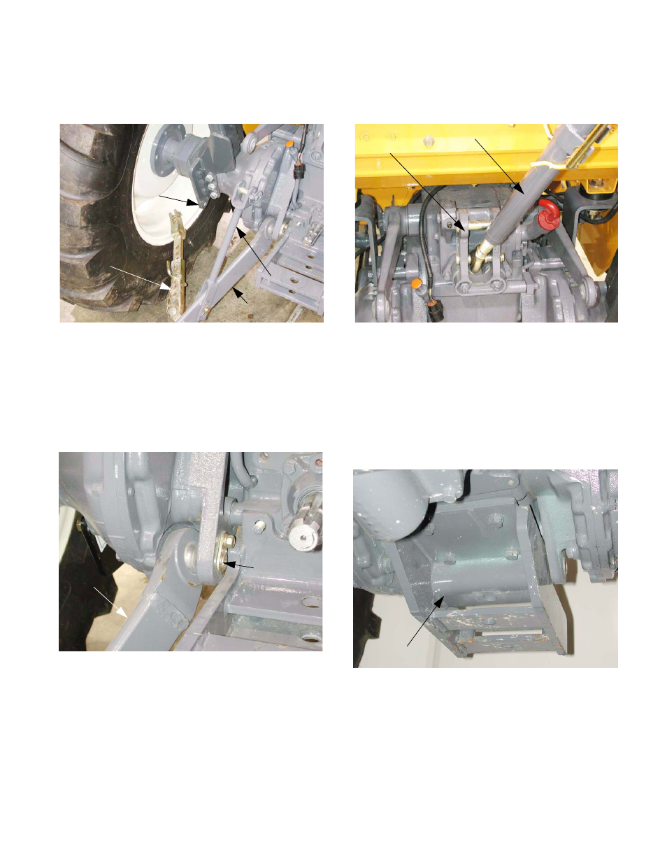
1.14. Disconnect the lower link limiter from the
R.O.P.S. bracket on the axle by removing the
hairpin clip and clevis pin. See Figure 1.14.
1.15. Disconnect the lower link lift rod from the lift arm
by removing the click pin and clevis pin. Allow
the lower link to rest on the ground.
1.16. Remove the bolt that secures each lower link
pivot pin using a 14 mm wrench.
See Figure 1.16.
1.17. Withdraw each pivot pin and remove each lower
link.
Figure 1.14
Lower link limiter
Bracket
Lower Link
Lower link
lift rod
Figure 1.16
Lower link
Pivot pin
1.18. Remove the hairpin clip and clevis pin that
secure the top link to the draft control input
bracket. See Figure 1.18.
1.19. Remove the top link.
1.20. Install the two nuts that held the P.T.O. shield
and draw bar bracket to the back of the trans-
mission housing. Put them on finger-tight only.
1.21. Remove the four bolts that hold the draw bar
bracket to the bottom of the transmission hous-
ing using a 19mm wrench. See Figure 1.21.
1.22. Leave the draw bar bracket in position. It will
hang securely on the two studs on the back of
the transmission housing.
1.23. Position the backhoe latching bracket beneath
the draw bar bracket, using a hydraulic jack.
Figure 1.18
Top link
Draft control
input bracket
Figure 1.21
Draw bar bracket