Cub Cadet 8000 Series User Manual
Page 13
9
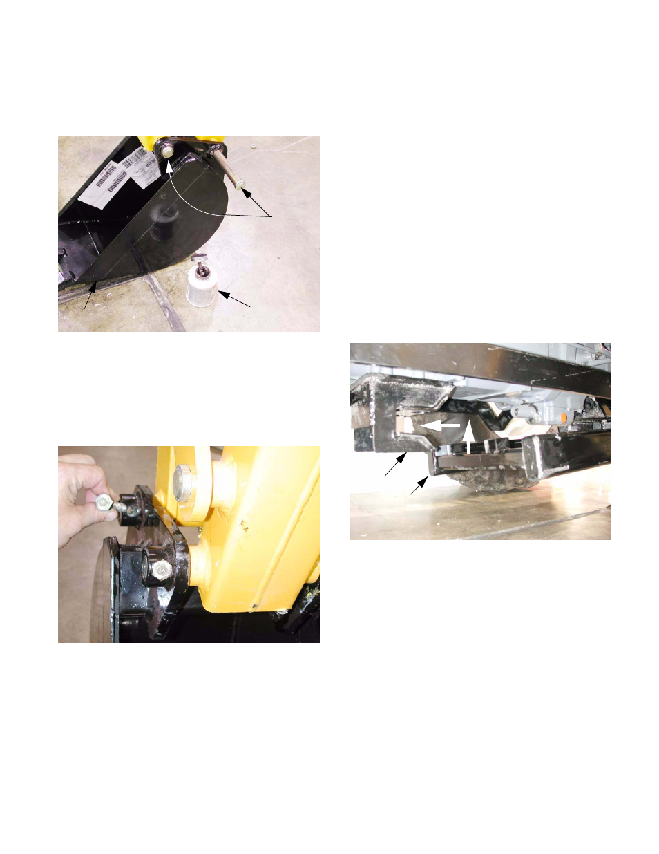
1.67. If no leaks exist, re-start the engine, lower the
stabilizers and manipulate the boom and dipper-
stick to allow the installation of the bucket.
See Figure 1.67.
NOTE: It is generally easier to connect the
bucket to the fixed portion of the dipperstick first.
1.68. Secure the bucket to the dipperstick using the
large pins. Lock the pins in place using the nuts
and bolts provided in the kit. See Figure 1.68.
NOTE: There may be some interference
between the hardware and the weld beads on
the collars that the bolts pass through. This is
acceptable, and creates and additional locking
effect.
1.69. Once the bucket is installed, it may be used in
conjunction with the stabilizers to raise the
Figure 1.67
Anti-seize
compound
Bucket
Pin
Figure 1.68
mounting frame up to just beneath the level of
the latching bracket and receiver.
1.70. Ensure that the hydraulic hoses are clear of the
wheel paths, and back-up the tractor until the
center cross member of the mounting frame is
just behind the latching bracket.
1.71. Check the final alignment of the front cross
member with the receiver. It should be roughly
centered.
NOTE: small lateral adjustments can be made
using the swing of the boom. Larger adjust-
ments will require realignment of the tractor.
1.72. Using the stabilizers and bucket, raise the
mounting frame to make the final height adjust-
ment. The front cross-member of the mounting
frame should be level with the receiver. The
center cross-member should be level with the
latching bracket.
1.73. Once correct alignment is achieved, back the
tractor into the mounting frame, seating the cen-
ter cross member into the latching bracket.
Figure 1.72
1
2
Receiver
Front Cross member