Cub Cadet 8000 Series User Manual
Page 8
4
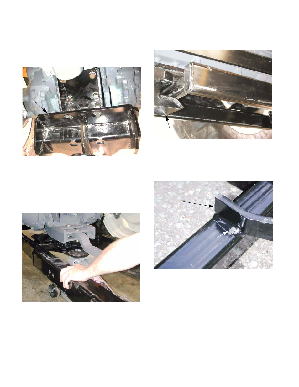
1.24. Fasten the latching bracket and draw bar
bracket to the bottom of the transmission hous-
ing using the six 14 mm by 40 mm bolts and
lock washers provided with the back-
hoe. See Figure 1.24.
NOTE: Use a 22mm wrench to tighten the bolts.
1.25. Test fit the mounting frame. Lift it into position
using a hydraulic jack, and confirm the correct fit
of the frame in the receiver and latching bracket
when they are mounted on the tractor.
See Figure 1.25.
NOTE: The draw bar may be left in or removed,
at the operator’s or installers discretion. The
draw bar can be installed or removed once the
backhoe is mounted, but it is difficult to reach the
hairpin clips that secure the clevis pins.
1.26. Confirm that the mounting frame seats properly
in the receiver. See Figure 1.26.
1.27. Confirm that the mounting frame seats fully into
the latching bracket, allowing the T-handle clevis
pins to drop completely to their stop shoulders.
See Figure 1.27.
NOTE: If there is a fit problem, the test fit will
help identify the source of the issue.
NOTE: If the mounting frame does not fit prop-
erly, it may be necessary to radius some welds,
or adjust the mounting positions of the receiver
and latching bracket. If these minor adjustments
do not solve the problem, call Cub Cadet Techni-
cal support.
Figure 1.24
Mounted
latching bracket
Figure 1.25
Figure 1.26
Mounted
Receiver
Test fit mounting frame
Figure 1.27
Witness mark from
weld interference
Guide tab at front
of mounting frame