Cub Cadet 8000 Series User Manual
Page 12
8
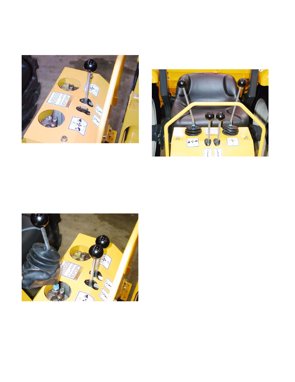
1.58. Thread the stabilizer control levers into the link-
ages inside the two close-set holes in the top of
the console. See Figure 1.58.
1.59. Once installed, tighten the jam nuts using a
14mm wrench.
1.60. Start the two levers that control the boom, swing,
dipperstick and shovel control levers through
their rubber boots and bushings.
1.61. thread the two levers into the linkages visible
within the two larger holes in the console cover.
See Figure 1.61.
1.62. Each of the two levers has a slight bend in it.
Position the two levers so that they are angled
away from one another.
1.63. Tighten the jam nuts using a 14mm wrench to
secure them in this position.
1.64. Tuck the bottom of each rubber boot into the
hole surrounding each control lever, to help keep
out water and dirt. See Figure 1.64.
1.65. Ensure that no unsafe conditions will arise from
starting the engine or operating the backhoe.
1.66. Start the engine briefly, and check for any
hydraulic leaks. Turn off the engine, relieve
pressure, check for and repair any leaks before
continuing.
NOTE: Mounting the backhoe to the tractor is
the only time that it is recommended to operate
the backhoe while not occupying the operator’s
seat.
Figure 1.58
Figure 1.61
Figure 1.64