Cub Cadet 8000 Series User Manual
Page 10
6
1.35. Remove the two seat brackets from the seat
pedestal using a pair of 13mm wrenches.
1.36. Place the backhoe seat atop the pedestal, and
secure it by running 5/16” bolts with lock wash-
ers through the holes previously occupied by the
seat bracket bolts, and into the threaded holes in
the bottom of the seat. See Figure 1.36.
1.37. Tighten the bolts using a 1/2” wrench. They are
easily reached once the threads are started by
tilting the seat forward.
1.38. Remove the cover from the backhoe control con-
sole using a pair of 13mm wrenches.
See Figure 1.38.
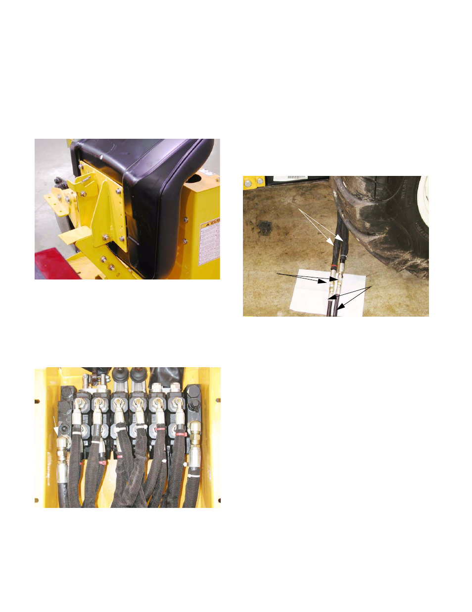
1.39. Identify the feed and return lines where they
enter the hydraulic valve package. As see from
behind the backhoe, looking toward the front of
the tractor, the feed line is on the right side,
entering the middle port of the valve. The return
line is on the left, entering the lowest port on the
valve.
1.40. Connect the hoses on the backhoe to the two
separate lengths of hose that came with it, keep-
ing track of which hose is which. Connect the
hoses using two 3/8” JIC unions.
See Figure 1.40.
1.41. Tighten the fittings using a 7/8” wrench and a 13/
16” wrench.
1.42. If the loader had been previously installed, per-
form the following steps:
1.43. Disconnect the loader return hose and the 90
degree fitting from the adaptor on the front sur-
face of the modulating valve.
Figure 1.36
Figure 1.38
Feed
line
Return
line
Figure 1.40
3/8” JIC Unions
Hoses from backhoe
Additional
lengths of hose