Warning – Cub Cadet 190-209-100 User Manual
Page 14
14
USING THE CASTER WHEELS TO SET CUTTING
HEIGHT
WARNING
Before making any adjustments to the cutting
height setting, place the PTO switch in the
“OFF” position, engage the parking brake lever,
and turn the ignition key to the “OFF” position.
Use care not to cut yourself on the sharp blades.
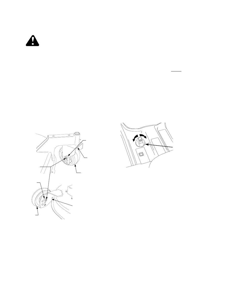
The cutting height is set by positioning the front caster
wheels in one of five settings in the caster wheel yoke
of the deck (See Figure 22). The setting holes equate
to height settings ranging from approximately 1-1/2”
(upper hole) to 3-1/2” (lower hole), with the holes
positioned at 1/2” increments.
Set the cutting height as follows:
1.
Remove the hex cap screws and nylon lock nuts
from the front caster wheels and caster wheel
yokes (See Figure 22).
Figure 22
2.
Align the caster wheels with the holes in the yoke
that correspond to the desired cutting height.
Insert the hex cap screws and secure with the
nylon lock nuts.
3.
Remove the hex cap screws and nylon lock nuts
from the rear gauge wheels and gauge wheel
brackets (See Figure 22).
4.
Note the hole position of the front caster wheels
and align the rear gauge wheels with the matching
holes in the gauge wheel brackets. Insert the hex
cap screws and secure with the nylon lock nuts.
If a cutting height in excess of 3-1/2” is desired, it will
be necessary to set the cutting height by positioning
the deck using the tractor lift system or, if applicable,
the deck downstop feature. The wheels will not contact
the ground.
USING HEIGHT ADJUSTMENT KNOB — TRAC-
TORS WITH DECK DOWNSTOP ONLY
A full rotation of the height adjustment knob equals ap-
prox. a 1/4 inch adjustment in the deck height setting.
There are four detent positions per rotation. Initially set
the deck downstop as follows (Refer to Figure 23):
1.
To remove the weight of the deck from the downstop
arm, use the tractor lift system to raise the deck.
Move the caster wheels and rollers to their highest
position.
2.
Fully lower the deckstop by continuously turning
the height adjustment knob counterclockwise.
Figure 23
3.
Use the tractor lift system to lower the deck to the de-
sired height setting, then turn the adjustment knob
clockwise until it stops turning freely. Turn the knob to
nearest detent position.
4.
Reposition the caster and gauge wheels so that
they are appoximately 1/2 inch above the ground.
5.
For subsequent minor adjustments from this
position, use the tractor lift system to raise the deck,
then turn the adjustment knob as necessary to
attain the desired height setting (one full turn
equals approximately 1/4"). Reposition the caster
and gauge wheels if necessary.
USING THE CASTER WHEELS ON TRACTORS
WITH DECK DOWNSTOP
To use the caster and gauge wheels for setting the
cutting height on tractors equipped with the deck
downstop, make certain to lower the downstop using
the height adjustment knob. Then follow the previous
instructions for setting the cutting height using the
caster wheels.
CASTER
WHEEL
YOKE
FRONT
CASTER
NYLON
LOCK NUT
HEX CAP
SCREW
REAR
GAUGE
GAUGE
WHEEL
BRACKET
NYLON
LOCK NUT
WHEEL
WHEEL
RAISE
LOWER
HEIGHT
ADJUSTMENT
KNOB