Warning – Cub Cadet 190-209-100 User Manual
Page 11
11
Figure 14
13. Initial installation only. Tighten the hex lock nuts
on the front lift rod until the rod just contacts the
front of both slots in the deck front roller bracket.
For now, tighten the hex jam nuts and lock
washers until just snug against the front lift
bracket. Refer to Adjustments—Section III for
final adjustment of front lift rod.
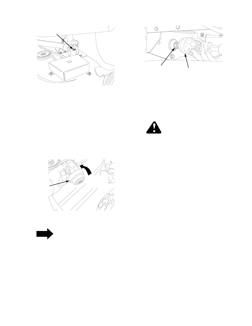
14. Compress the auto-lok collar of the deck drive
shaft rearward, then cock to lock the collar in the
released position (See Figure 15).
Figure 15
NOTE
If you do not lock the drive shaft auto-lok collar
in the released position (step 14), it will be
necessary to compress and hold the collar
rearward when connecting the shaft (step 15).
15. Slide the deck drive shaft fully onto the PTO shaft
of the tractor (See Figure 16). The auto-lok collar
of the drive shaft should snap into the locked
position when the shaft is properly positioned on
the PTO shaft.
16. Refer to Adjustments— Section III for mower
deck leveling adjustment procedures.
Figure 16
B. REMOVAL OF DECK
Place the tractor and mower deck on a firm and level
surface with enough room to slide the deck out from
the left side of the tractor.
WARNING
Before removing the mower deck, place the
PTO switch in the “OFF” position, engage the
parking brake lever, and turn ignition key to the
“OFF” position. Always stop the engine after
utilizing the tractor hydraulic lift system. When
handling the deck, be careful not to cut yourself
on the sharp blades.
1.
Support the deck drive shaft, then pull the auto-lok
collar rearward and slide the drive shaft off of the
PTO shaft (See Figures 15 and 16).
2.
Check that the caster wheels and gauge wheels
are in their highest setting (lowest deck setting). If
necessary, remove the hex cap screws and nylon
lock nuts and adjust the wheels.
3.
Use the tractor lift system to lower the deck to the
ground. NOTE: If removing the deck from a tractor
with the deck downstop, make certain the downstop
is in the lowered position (Refer to Section 1 ).
4.
Pull outward and cock the deck support pins in the
deck hanger brackets so that both pins are held in
the disengaged position against the inner surface
of the deck brackets (See Figure 8).
5.
Lock the left lift link in its deck installation/removal
position as follows:
a.
Holding the left lift rod downward, lift upward
on the release tab of the lift stop bracket while
raising the rearward end of the lift link to align
the notch of the rod with the slot of the link
(See Figures 4A and 4B).
b.
Swing the lift rod forward until fully to the front
of the lift link slot (See Figures 4C and 4D).
SUPPORT PIN EXTENDED
THROUGH LIFT LINK
AUTO-LOK
COLLAR
COMPRESS
THEN COCK
TO LOCK
DECK DRIVE
SHAFT
PTO SHAFT