Cub Cadet 190-209-100 User Manual
Page 13
13
5.
Side to side leveling is attained by adjusting the
hex lock nut on the bottom of the LH lift rod,
located below the LH lift link (See Figure 19).
6.
Turn the hex lock nut upward (tighten) on the
threads of the lift rod to raise the left side of the
mower deck. Turn the lock nut down (loosen) on the
threads to lower the left side of the mower deck.
7.
Recheck the measurements described in step 4. If
the blade measurements are not within 1/16 inch,
repeat steps 4 and 6 until the correct
measurement is obtained.
Figure 19
B. FRONT TO BACK LEVELING ADJUSTMENT
Although the 44” mower deck is designed to run on the
front caster wheels, the front lift rod must be correctly
adjusted to ensure the deck maintains the proper pitch
when mowing uneven terrain.
1.
Using the tractor’s lift system, raise the deck to one
of the higher cutting positions. Make certain the
front caster and rear gauge wheels do not touch
the surface below.
2.
Position the mower blades so the ends of each
blade point to the front and the rear of the tractor
(See Figure 20).
Figure 20
3.
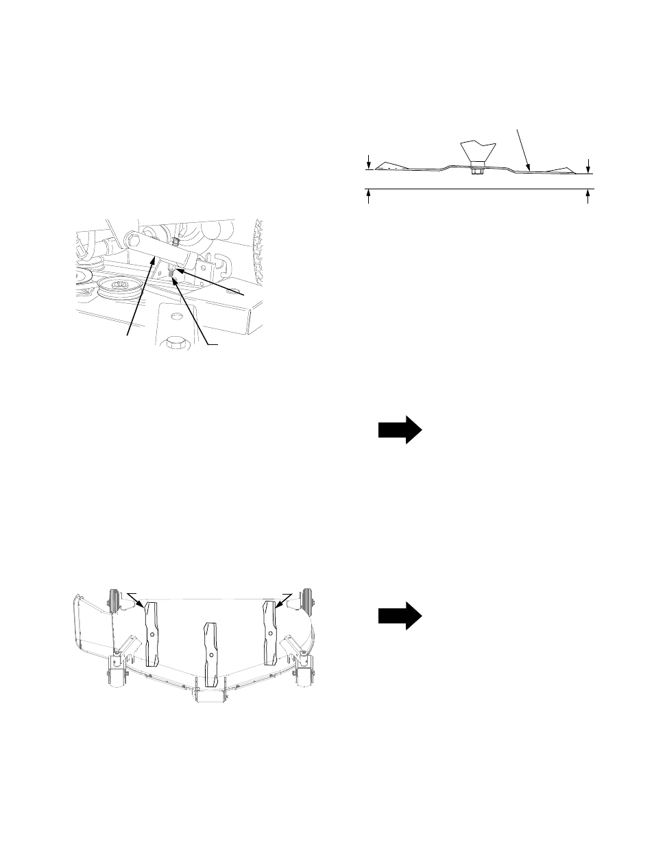
Refer to Figure 21. Measure and record the
distance from the front cutting edge to the ground
(measurement A), and from the rear cutting edge
to the ground (measurement B), for both outer
blades. The front edge of each blade
(measurement A) should be lower than its back
edge (measurement B) by approximately 1/8 inch.
Figure 21
4.
Adjust the front lift rod as follows to attain the
proper pitch of the mower deck. Refer to Figure 10
if necessary.
a.
Loosen the hex jam nuts and lock washers on
the front lift rod.
b.
From the front of the tractor, turn the front hex
lock nuts clockwise to raise the front of the
deck, or counterclockwise to lower the front of
the deck.
c.
Recheck the measurements described in step
3 and readjust the hex lock nuts until the
proper measurements are obtained.
NOTE
The front lift rod should be fully to the front of both
slots in the deck front roller bracket. If one side of
the rod does not contact the front of the slot,
tighten the corresponding lock nut as needed.
5.
Tighten the rear jam nuts and lock washers
against the backside of the front lift bracket after
adjustment of the rod has been completed.
C. SETTING THE CUTTING HEIGHT
NOTE
Cutting height adjustment should be performed only
AFTER the mower deck has been properly leveled.
If the mower deck is installed on a tractor without the
deck downstop feature, the cutting height is set by
positioning the front caster wheels in one of five
settings in the caster wheel yokes.
If the deck is installed on a tractor with the downstop
feature,
the
cutting height is set by using either the
deck height adjustment knob to set the deck downstop
position or by positioning the caster wheels in one of
five settings.
HEX LOCK NUT
LH LIFT ROD
LH LIFT LINK
OUTER BLADES
POSITIONED FRONT TO REAR
B
A
FRONT
CUTTING
EDGE
REAR
CUTTING
EDGE
CUTTING BLADE