Cub Cadet 190-209-100 User Manual
Page 10
10
NOTE
The following step 8 and step 13 apply only to
the initial installation of the deck on the tractor.
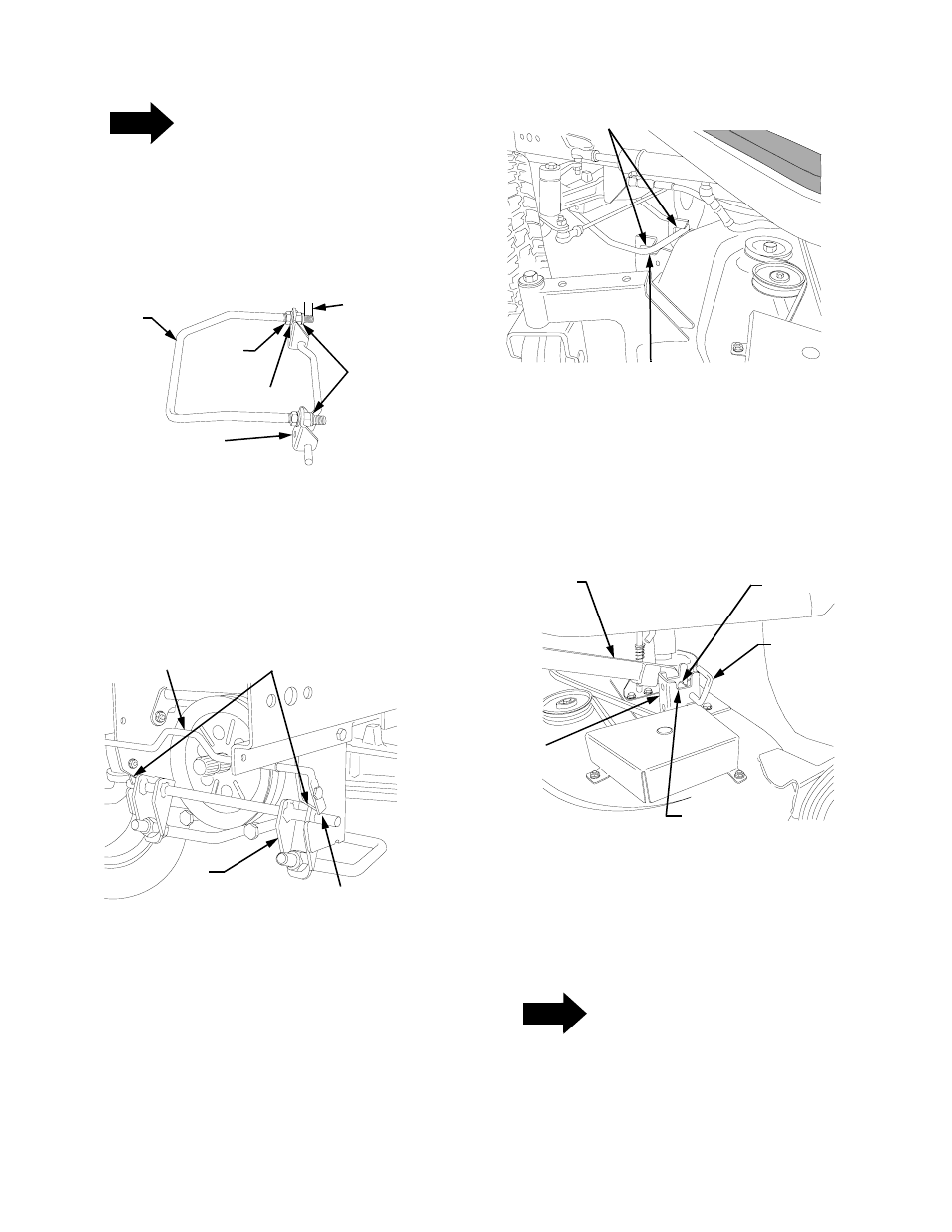
8.
Loosen the hex jam nuts on the front lift bracket/
rod assembly and turn the hex lock nuts until
approximately 1/2 inch from the ends of the
threads (See Figure 10).
Figure 10
9.
From the front of the tractor, slide the outer pins of
the front lift bracket into the latch receiver slots of
the tractor. Press the lift bracket rearward until
both sides are firmly captured in the latch receivers
by the quick latch rod (See Figure 11).
Figure 11
10. From the side of the tractor, raise the front lift rod
and roll the deck forward until the lift rod aligns with
slots of the deck front roller bracket. Lower the lift
rod into the front roller bracket slots and slide the
deck rearward to engage the lift rod fully forward
in the slots of the roller bracket (See Figure 12).
Figure 12
11. Guide the LH and RH lift links into the slots of the
rear deck brackets and release the deck support
pins by aligning with the inner holes of the deck
brackets (See Figure 13). Make certain the
handles of the support pins are within the notches
at the top of the rear deck brackets.
Figure 13
12. Maneuver each side of the deck slightly to align the
support pins with the holes of the lift links. The
spring tension will push the pins inward and, if
aligned, through the hole in each implement lift
link (See Figure 14).
NOTE
If unable to align the support pins with the lift
link holes, loosen the two hex lock nuts on the
front lift rod to allow the deck to be moved
farther rearward.
FRONT
LIFT
FRONT LIFT
BRACKET
HEX
LOCK WASHER
HEX
LOCK
NUTS
JAM
NUT
ROD
APPROX.
1/2 INCH
QUICK LATCH ROD
LATCH RECEIVER SLOTS
FRONT
LIFT
BRACKET
CAPTURE IN
RECEIVER SLOTS
FRONT ROLLER
BRACKET SLOTS
FRONT LIFT ROD
INNER HOLE
REAR
DECK
BRACKET
LIFT LINK
DECK
SUPPORT
PIN
NOTCH