COP-USA ASH65NV User Manual
Page 14
The third step is to fix the mounting plate with the pan/tilt on the ground. Take care
that wires should be put into the groove under the mounting plate to avoid to be
pressed. It is shown as Figure 3.5.3.
Figure 3.5.3
6. Connections
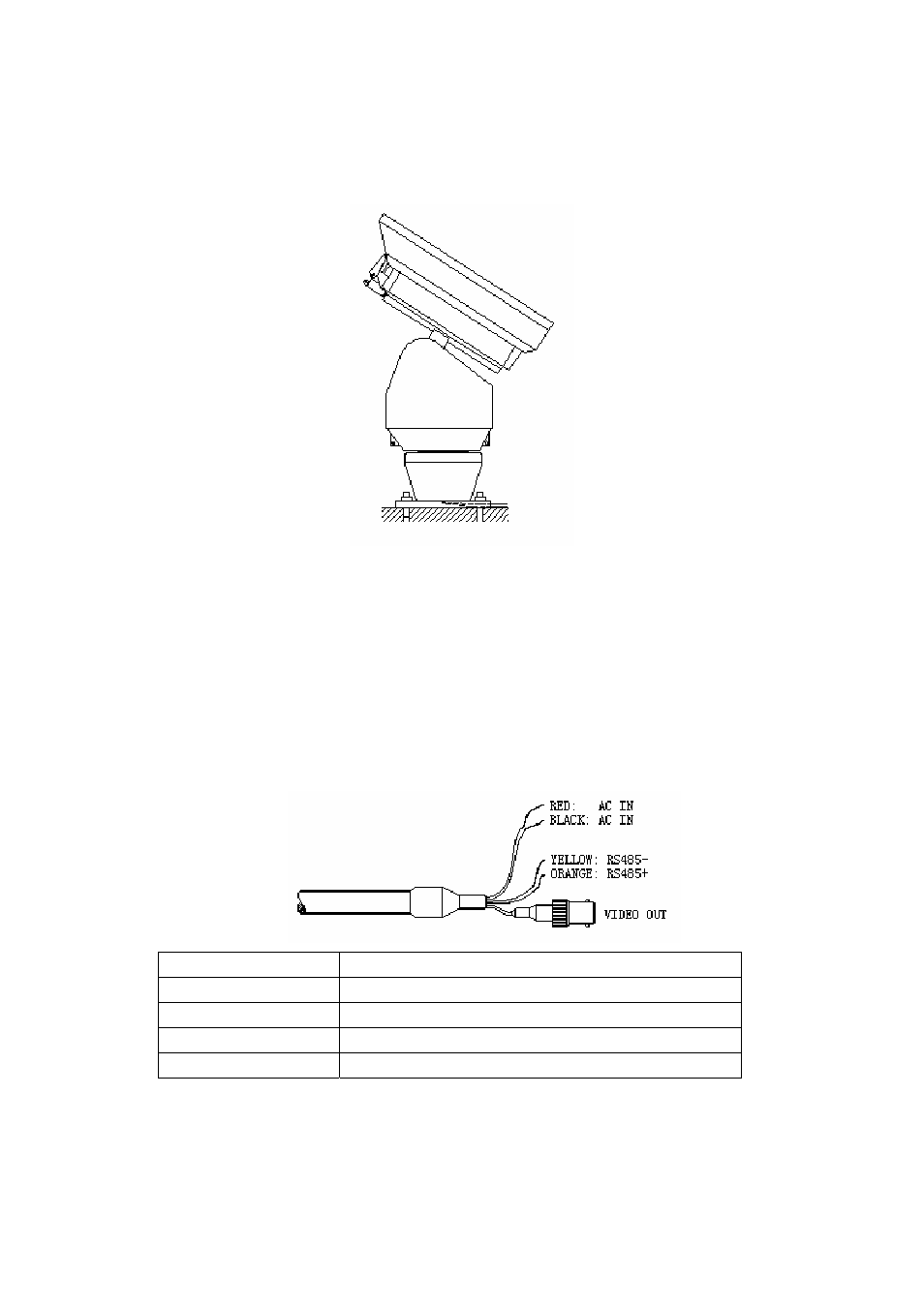
Please refer to the descriptions of following drawing.
1) System Wires
RED
Input of AC Power Supply
BLACK
Input of AC Power Supply
YELLOW Control
Wire
RS485-(B)
ORANGE Control
Wire
RS485+(A)
VIDEO OUT
Video Output
2) Alarm Wires
10