COP-USA ASH65NV User Manual
Page 11
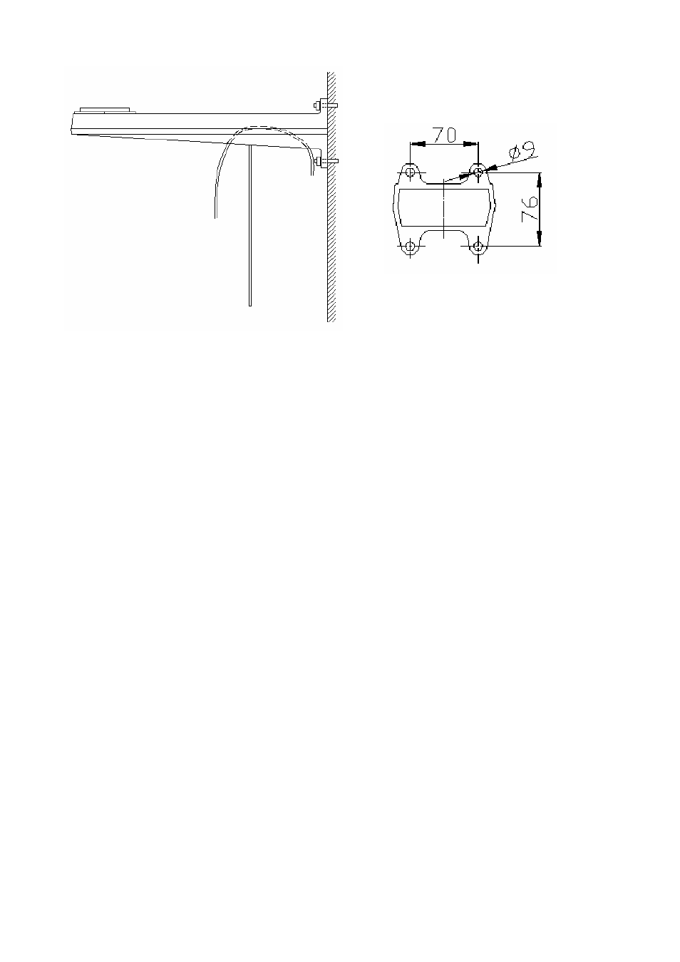
Figure 3.4.1
Figure 3.4.2
It is suggested to mount the support with M8 screw.
There is a mobile plate under the support. It can be laid down if screws on the front
are taken off. Lead wires of the system into the support for connection.
The second step is to put the pan/tilt on the support and tighten screws upward
beneath the support, shown as in Figure 3.4.3.
Please take M6×20 screw.
The third step is to connect output wires of the pan/tilt and the system, wrap the joints
by insulation tape and fix the mobile plate under the support.
It should be like what Figure 3.4.4 shows.
7