Iv. setup of the intelligence full-dome pan/tilt – COP-USA CD56NV-IR User Manual
Page 8
deleted. When calling the preset position, it only displays “NO.XXX”
without the title.
IV. Setup of the Intelligence Full-Dome Pan/Tilt
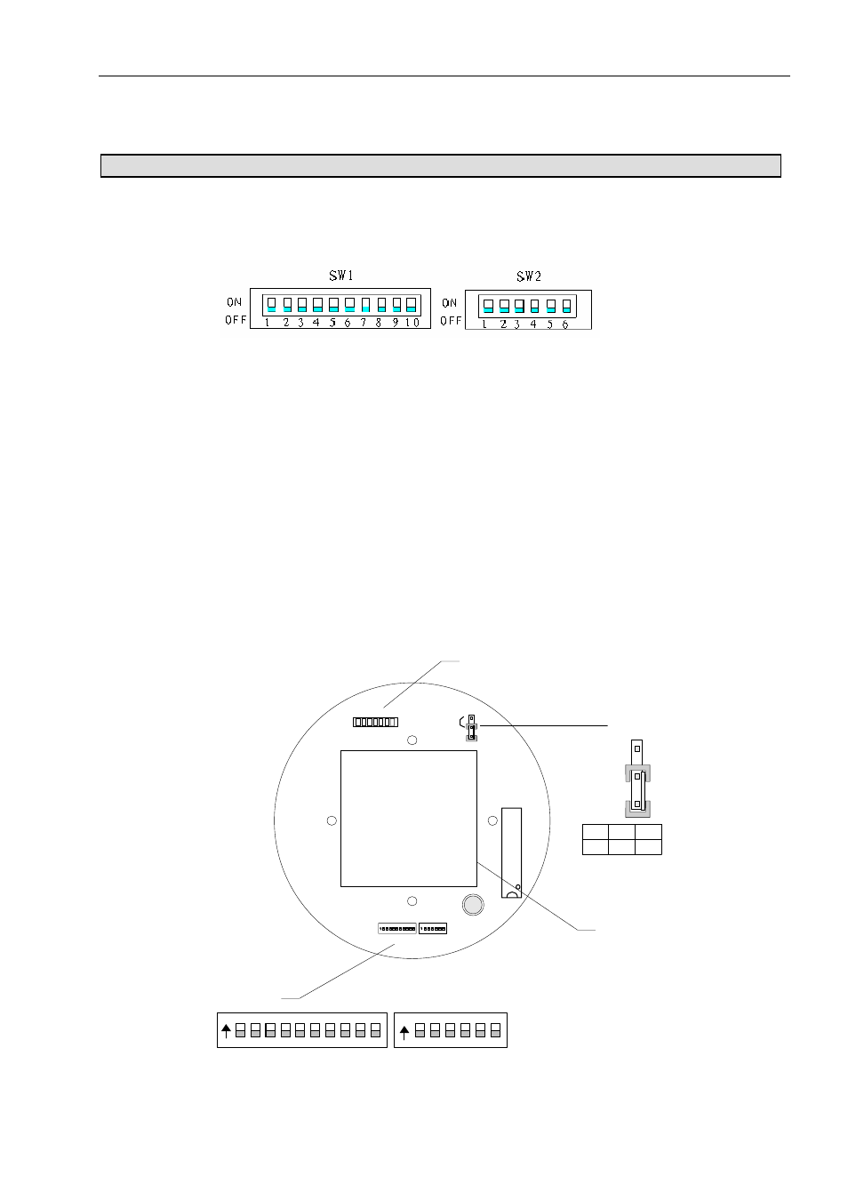
Before installing the product, first of all confirm the communication protocol and the baud rate of the main
machine in the system, then set the dip-switch SW2 of the pan/tilt to be identical with that of the system, set the
address of the pan/tilt on SW1 and the type of the communication protocol and the baud rate on SW2.
Dip-Switch of Address Dip-Switch of Protocol
(Figure 1)
1. Terminal Resistor:
The jumper JP1 is the option switch of 120 Ω terminal resistor of the bus RS485. When it is at 2—3 state, 120
Ω terminal resistor is opened and no bus 485 is connected; when it is at 1—2 state, 120 Ω terminal resistor is
connected in parallel with the bus 485. In the bus RS485 system, there is only one pan/tilt, which has the terminal
resistor to be connected in the circuit and other pan/tilts whose terminal resistors are opened so as to increase the
reliability of the system. Generally, the terminal resistor of the pan/tilt at the farthest end from the control circuit is
connected and all terminal resistors of other devices are opened.
2. Power Supply Panel for the Vehicle Pan/Tilt:
a. Input voltage is DC10.5-18V, I
in
≥3.5A;
b. No alarm input and output.
JP1 1-2 2-3
120R ON OFF
ON DIP
1 2 3 4 5 6
ON DIP
1 2 3 4 5 6 7 8 9 10
JP1
1
2
3
Code
JP
1
DC/DC
Converter
1
2
3
connect
3.Power Supply Panel for the Vehicle Pan/Tilt:
:
a. Input voltage is AC24V, I
in
≥1.75A;
7