Installation – COP-USA CD55-SDI User Manual
Page 5
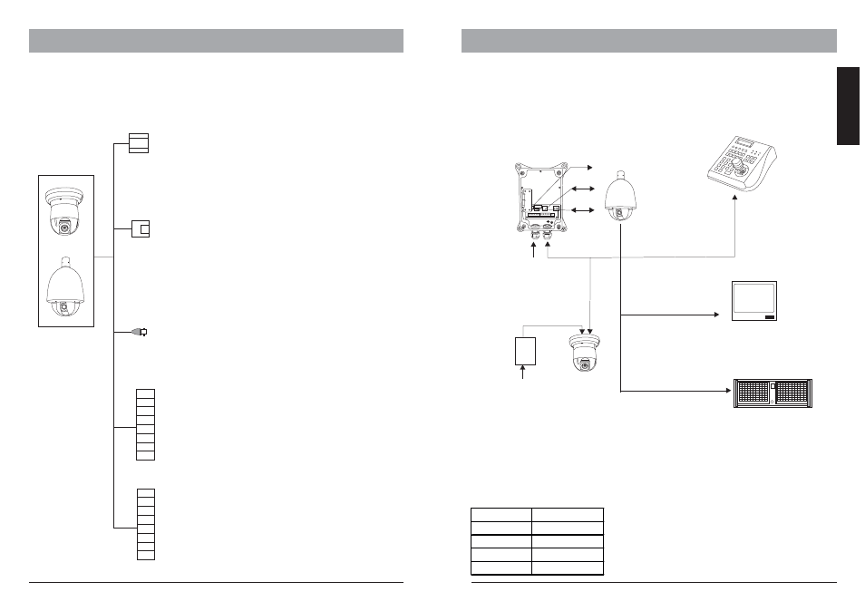
4.INSTALLATION
Connector description
The wiring cable of G65 and G70 provides connectors for power supply, video and I/O
interface
Video output
BNC
Inner Conn: Signal +
Outer Conn: Ground
HD-SDI Video Output to monitor or DVR
Using optional accessories
The High speed dome camera can be connected to various optional
accessories through the standard connector types, which simplifiy the cable handling
and avoids possible mistakes. All accessories are tested for max. compatibility and
best performance.
Outdoor power adaptor box
AC 230V to AC 24V
AC 24 Power
supply
RS 485
Alarm I/O
AC 230V
Power input
Indoor power adaptor
AC 230V to AC 24V
Power
Box
AC 230V
Power input
AC 24 Power supply
3-Axis keyboard
controller
RS 485
Telemetric control
camera setup
Monitor
21”High Res.
security Monitor.
DVR-Server
Professional Real-time
16 Channel DVR
Video signal
RS 485 cable
The telemetric control of the appliance uses Rs485 serial communication with half-
duplex transmission technology.
Depends on the cable typeand baud rate, the transmission distance could vary. The
following table shows max. distances based on cable with 0,56mm (24AWG) twisted
pair:
2400 bps
1100 m
700m
400m
4800 bps
1700m
9600 bps
19200 bps
Baud Rate
Max. Distance
Due the environmental interferences, such as
eletromagnetic and induction fields, or number of
connected appliance on the RS-485 bus, the
transmission range may be less, e.g with cable thinner
than than 24AWG.
4.INSTALLATION
5
6
ENGLISH
Power
Connector
RS485
Connector
RJ-11
Alarm I/O 1
RED: AC 24V
BLACK: AC 24V
To power supply
Green:RS485+
Yellow:RS485-
To Keyboard or DVR decives for
telemetric control
RED: Alarm in 1
PINK: Alarm in 2
YELLOW:
GREEN:
BLACK: COM
WHITE: Alarm output - N.O
BLUE: Alarm output - N.C
AQUA
Alarm in 3
Alarm in 4
:
I/O interface to additional alarm sensor
or control devices
Alarm output - N.C2
BROWN: Alarm output - N.O2
GRAY: Alarm in 7
PURPLE: Alarm in 6
ORANGE: Alarm in 5
Alarm I/O 2