Checkline SY User Manual
Page 4
4
5
3 .0 P
REPARI N G
SY T
EN SI OM ET ER
C
ALI BRAT I ON
C
H ART S
/C
U RV ES
3.1 Material
Required
1. Test Span Sample of 14-ft (minimum) of the installed cable, where long
cables are involved. Where installed cables are less than 14-feet long,
use a test span equal to the length of the cable.
NOTE: Application spans of less than 14-feet, great stiffness and/or
large diameter may not be measurable. Please inquire.
2. Turnbuckle, winch or hydraulic tensioning system of sufficient load capacity
for the application.
3. An in-line tension-reading device, such as a certified dynamometer or load
cell with indicator.
4. Rigid attachment structure, to withstand the full tensile loads.
5. Attachment hardware for all cable ends and devices.
3.2 Procedure
1. Set up the load cell, or other readout device, so that its indicator reads “0”.
2. The pointer of the Tensiometer dial indicator should read “0”. If not, rotate
the outer bezel of the indicator until it does read “0”.
3. Set up the test cable sample, load-applying device and the inline tension
read-out device, as indicated in Figure 2., SY Tensiometer Calibration Setup,
below.
4. Before hanging the SY Tensiometer being calibrated on the cable, lower the
middle roller to provide clearance between the dial indicator shoe and the
middle roller for the test cable, by turning the knurled CF screws head
clockwise (CW) until the middle roller retracts sufficiently to provide the
needed clearance.
5. Hang or hold the SY Tensiometer so that the test cable passes under
the outer rollers and over the middle roller. The inline indicator will
show a minimum tension, resulting from the weight of the cable and
the tensiometer itself.
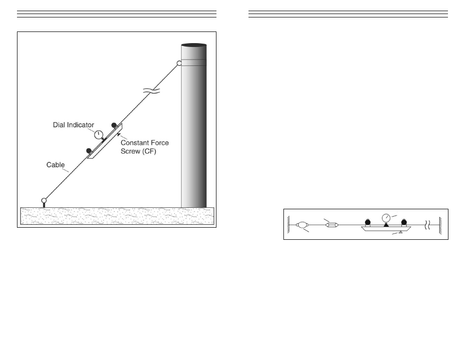
Dial Indicator
Constant Force Screw (CF)
Figure 2. SY Tensiometer Calibration Setup
Dynamometer
Turnbuckle
Figure 1. SY Tensiometer Measuring Setup