Checkline SY User Manual
Page 3
3
2 .0 O
PERAT I N G
I
N ST RU CT I ON S
NOTE: The following instructions are somewhat detailed, to make them very clear
for the first time user. Be assured that the operations described are very simple and
easy to perform. After a couple of repetitions of the procedure, it should not take more
than a minute to complete a measurement.
1. Adjust the pointer of the Tensiometer’s Dial Indicator to “0” by rotating the outer,
knurled rings of the lens bezel.
2. Referring to Figure 1. SY Tensiometer Measuring Setup, below, turn the knurled
“constant force” (CF) screw clockwise (cw) to lower the middle, “sensing” roller
sufficiently to clear the Dial Indicator shoe and the cable to be measured. The
Tensiometer should then be hung on the cable by passing it under the outer
“reference” rollers and over the middle “sensing” roller, without contacting the
indicator shoe. (If the cable is vertical or slanted, the Tensiometer should be held,
or blocked with a “C” clamp, to prevent movement, until the next step is
completed).
3. With the Tensiometer hung on the cable, or held in place, turn the CF screw
counter-clockwise (ccw) until the middle roller deflects the cable completely and
there is no further movement of the dial indicator pointer. Continue rotating the CF
screw for one more turn. This action applies the full constant force midway
between the two outer rollers during the measurement.
4. If TENSION MEASUREMENT* is being made, refer to the previously made SY
Calibration Chart/Curve to determine the tension in the cable. If tension adjustment
is needed, note the required cable deflection for the tension desired by referring to
the calibration chart/curve and then adjust the cable tension until the dial indicator
reads the corresponding cable deflection.
5. If only TENSION COMPARISON or BALANCE* measurement is being made,
note the indicator cable deflection reading and compare it with that made on the
similar “standard” cable that has been tensioned to an acceptable tension. If the
deflection difference is not acceptable, adjust tension in the cable being checked
until the deflection reading is the same or nearly the same as with the “standard”
cable.
6. To remove the Tensiometer, reverse the process by turning the CF screw clockwise
(cw) until the middle roller drops sufficiently to clear the indicator shoe and cable
plus some more to clear the outer rollers when the unit is lifted slightly and pushed
back to clear the cable.
7. After measurements have been completed and before storing the Tensiometer,
turn the CF screw clockwise (cw) until the Dial Indicator foot is between 1/4"
to 1/2" from the middle roller. To protect the dial indicator during storage or
shipping, do not leave its foot in contact with the roller.
* Refer to introductory remarks on page 2 of these instructions.
6
6. Turn the CF screw head counter-clockwise (CCW) until the middle roller
reaches the cable. Continue turning until the dial indicator pointer value
reaches its maximum value, and then turn it another turn or two. This action
applies the pre-set Constant Force to the middle roller, causing maximum
cable deflection.
7.
Apply sufficient tension with the load-applying device, as indicated on the
load cell or dynamometer, to reach the first calibration point. (The user
should decide the minimum and maximum calibration points). Record the
cable deflection reading on a Load Vs Deflection chart.
8. Continue to apply tension at pre-selected intervals until maximum
tension values have been reached, recording deflections at each interval.
A corresponding Calibration Curve is recommended for easier reading
of values between intervals.
9. Remove the tensiometer by turning the CF screw clockwise until the middle
roller drops sufficiently to clear the indicator foot and cable plus some more
to clear the outer rollers when the unit is lifted slightly and pushed back to
clear the cable.
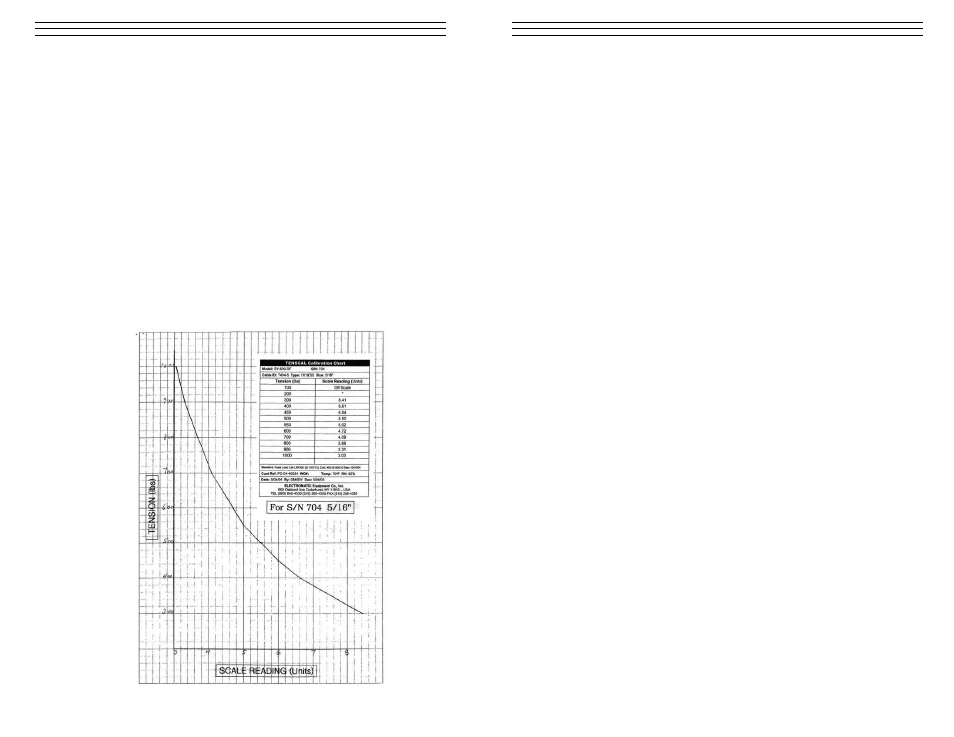
Figure 3 Sample Calibration Chart/Curve