Checkline DX2 User Manual
Page 6
6
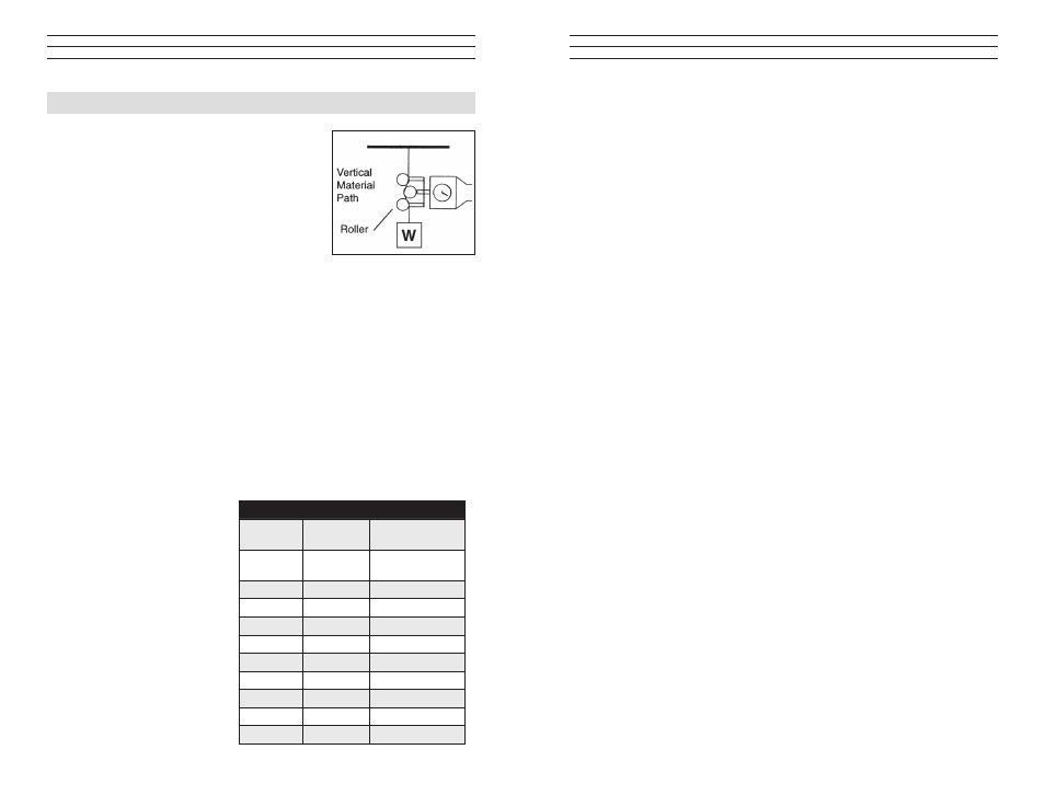
5.0 Calibration Notes
The calibration process involves hanging
laboratory weights from a fixed point, engaging
the vertical line material which holds the weights
with the tension meter 3-roller system, marking
a blank dial face where the scale pointer comes
to rest for each weight used, dividing the spaces
between load “reading” marks and finish marking
and numbering to show calibration marks and
“readings” on the dial face.
The procedure requires specialized skills and the following material:
1. A load stand to simulate the setup shown here.
2. A set of precision laboratory weights to cover the tension range of the
instrument.
3. Factory “standard” nylon monofilaments as shown in the Table on page 7.
4. A Calibration Kit which includes an Alignment Plate and two (2) special
metric wrenches.
A full, detailed calibration procedure is available upon request.
5.1 calibration with Factory standard Filaments
All DX2 Tension Meters are calibrated with laboratory weights suspended from
factory Standard nylon monofilament sizes, as noted in the table below. Any
difference in process material
size and rigidity from the
Standard materials may
result in some error. For
over 95% of applications,
the error is not significant
and can be ignored since
readings are generally treated
as production setup values
or are used for comparative
purposes. In those cases where
highest accuracy is required,
a correction chart showing
Readings vs. Actual Load
should be made up by the
user or “Special” calibration
should be specified when an
order is placed.
standard calibration monofilament sizes
Model
Range
(grams)
Monofilament
Dia. (mm)
DX2-5
5–50
1000 denier or
0.15 max.
DX2-12
10-120
0.20
DX2-20
10–200
0.20
DX2-40
10–400
0.25
DX2-SP
20–1000
0.30
DX2-EX
100–1000
0.30
DX2-200
200–2000
0.50
DX2-500
400–5000
0.80
DX2-1K
2–10 kg
1.00
DX2-2K
5–20 kg
1.20
7
5.2 special calibration
Special Calibration is optionally available for a specific material type and size so
long as the material fits the mechanical limits and range of the instrument. The
customer must supply a 10-ft. sample (3 meters) of the material. Such calibration
can be performed with or without using the Thickness Compensator if one has been
provided with the instrument. If not specified, the calibration facility will use its
best judgment.
NOTE: Special calibration is available for a single sample only.
5.3 NisT calibration
While all DX2 instruments are furnished with a Calibration Certificate which
certifies that they have been calibrated in accordance with factory procedures and
were found to meet all published accuracy specifications, such calibrations do
not fulfill ISO-9000 requirements since no record of measured values are kept or
are submitted. Where ISO-9000 requirements are to be met, NIST calibration is
optionally available but must be specified at time of order placement or after repair.
5.4 calibration Verification schedule
Frequency of calibration accuracy verification depends on many factors. These
include frequency and extent of tension overloads, operating speeds, length of
operating times, environment, care in handling, etc. Such determination is best
made by the user’s Quality Assurance Department based on the user’s experience.
However, a quick calibration check near the anticipated process tension levels
should be done to confirm the integrity of the instrument, as follows:
1. At the beginning of each work session
2. Every time a unit is dropped
3. Whenever process readings seem to be out of tolerance
for no apparent reason
The quick check can be made with a simple load stand, as shown in section 5.0,
using a sample of the process material and weights that are close to the tensions
encountered in the process. Be sure to move the tension meter up and down
slowly to simulate the motion of the running process material. This will check
the condition of the guide roller ball bearings and remove any inertia effect of
the movement. Readings that change with this motion reversal may indicate the
possibility of a guide roller ball bearing problem.
In the case of wire, which might be slightly deformed by the action of the 3-roller
system during static measurement, always move to a fresh portion of the wire each
time a measurement is made. (In production, the instrument always “sees” a fresh
portion.)