California Faucets Pressure Balance Valve User Manual
Page 2
PB-R_ii_110106.doc
Pg
2
1
2
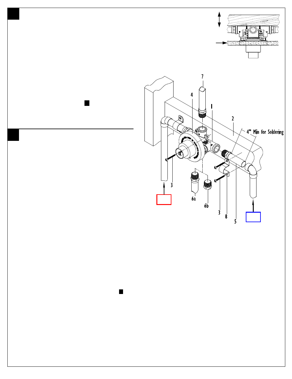
INSTALLING VALVE TO FRAME
• Determine the desired location for the valve,
construct suitable stud, and support framing
• Attach VALVE (1) to CROSS SUPPORT (2) by using
SCREWS (3) (not supplied) as shown
• The valve should be level in HORIZONTAL,
VERTICAL and PARALLEL to wall
• Placement of VALVE (1) and CROSS SUPPORT (2)
within the wall shall be determined by the MIN/MAX
limits shown on MUDGUARD (4)
• For complete detailed VALVE (1) dimensions and
recommended placement see .
5
. ROUGH-IN
DIMENSIONS
WATER
CONNECTIONS
• Pre-assemble FITTINGS (5) prior to attaching to
VALVE (1)
• Attach “C” INLET to COLD SUPPLY and “H”
INLET to HOT SUPPLY. All soldering of
FITTINGS (5) shall be performed a minimum
of 4” away from VALVE (1)
• Attach TUB PIPE (6a) to “T” OUTLET. Do not
use PEX or CPVC CTS piping from valve to
tub spout, as the reduced ID will result in too
much back pressure for valve to function
properly
• If valve is installed for SHOWER ONLY
configuration, attach PLUG (6b) to “T” OUTLET
• Attach SHOWER PIPE (7) to “S” OUTLET
• For additional support, use PIPE CLAMP (8) and
SCREW (3) (not supplied) at all attached pipe
connections
IMPORTANT: Flush supply lines prior to installation to prevent
damage and malfunction of pressure balance cartridge
IMPORTANT: If Cold and Hot supplies are not easily attachable to
desired inlet ports or for “Back-to-Back” installations, see .
4
.
MAINTENANCE
CAUTION: This valve contains plastic and rubber components. Do
not sweat or braze directly to the valve body. Do not apply excessive
heat to the valve body when you make solder connections. Do not apply
flux or acids directly to the valve, as damage to the seals, plastic
components, and trim finish may result
CAUTION: Inlet and outlet threaded joint connections should be
made with plumbers PTFE tape or liquid sealant. Oil-based, non-setting
compounds should not be used
Finished
Wall
HOT
SUPPLY
COLD
SUPPLY