Appendix – 360 Systems 2470SD Time Delay User Manual
Page 24
24
Broadcast Time Delay
Appendix
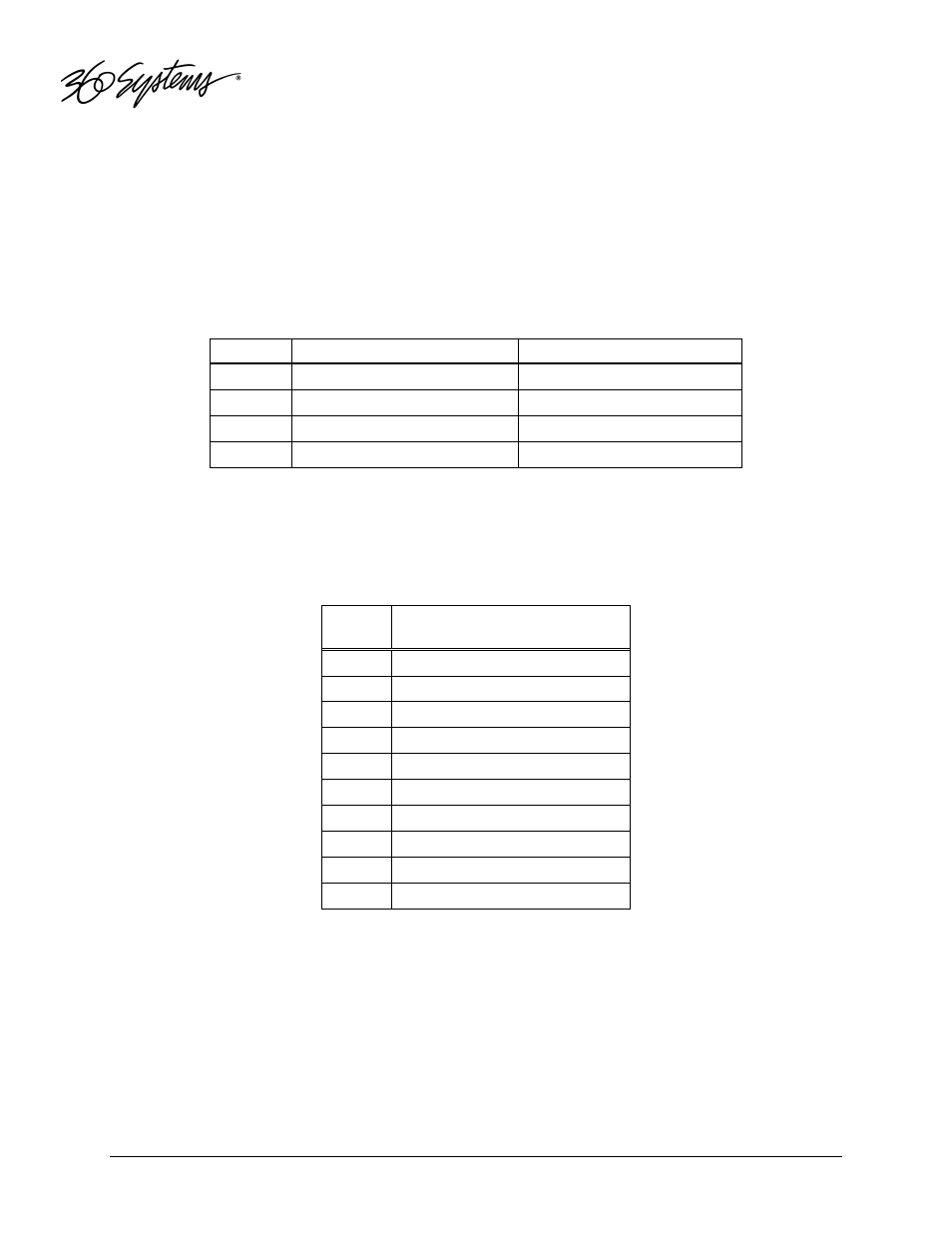
Audio XLR-3 Connector Pinout
The selection of analog or digital audio signals to appear on the XLR connectors is determined by the
setting of the internal audio selection jumpers on the internal audio PC card. The Pinout for the XLR
connectors is shown below.
Pin
BALANCED ANALOG
AES/EBU DIGITAL
1
SHIELD (frame ground)
SHIELD (frame ground)
2
" + " or HOT
Digital +
3
" – " or COMMON
Digital -
Shell
Frame ground
Frame ground
Serial Control Connector Pinout
Serial Control is currently used for factory testing only.
Pin
EIA-422, DB9-F
Connector
1
GND
2
Transmit A (TX–)
3
Receive B (RX+)
4
GND
5
N/C
6
GND
7
Transmit B (TX+)
8
Receive A (RX-)
9
GND
Shell
Frame ground
BNC Connectors
The following note applies to all video, LTC, and genlock connectors:
A BNC connector used as an output has a 75-ohm source impedance.
A BNC connector used as an input has a fixed 75-ohm termination.