Carrier 30GTN015-035 User Manual
Page 9
9
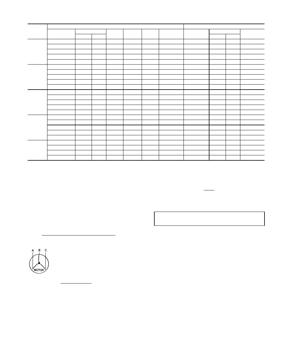
Table 3B — Electrical Data — Unit with Factory-Installed Motormaster® I Control
LEGEND
*Units are suitable for use on electrical systems where voltage sup-
plied to unit terminals is not below or above listed minimum and
maximum limits.
NOTE: Never operate a motor where a phase imbalance in supply
voltage is greater than 2%. Use the following formula to determine
the percent voltage imbalance.
Percent Voltage Imbalance
Example: Supply voltage is 240-3-60.
AB = 243 v
BC = 236 v
AC = 238 v
Determine maximum deviation from average voltage:
(AB) 243 – 239 = 4 v
(BC) 239 – 236 = 3 v
(AC) 239 – 238 = 1 v
Maximum deviation is 4 v. Determine percent voltage imbalance:
This amount of phase imbalance is satisfactory as it is below the
maximum allowable 2%.
UNIT
SIZE
30GTN
UNIT
CONTROL CIRCUIT
Voltage
V-Hz (3 Ph)
Supplied*
MCA
MOCP
ICF
Rec Fuse
Size
V-Hz
(Single Ph)
Supplied
MCA and
MOCP
Min
Max
Min
Max
015
208/230-60
187
253
82.2
125
278.4
100
115-60
104
127
30
460-60
414
506
38.3
60
129.3
45
115-60
104
127
30
575-60
518
633
30.8
50
105.6
40
115-60
104
127
30
380-60
418
342
43.9
70
152.8
60
230-60
198
254
15
380/415-50
342
440
51.9
80
181.5
70
230-50
198
254
15
020
208/230-60
187
253
97.4
150
357.4
125
115-60
104
127
30
460-60
414
506
49.6
80
182.3
60
115-60
104
127
30
575-60
518
633
42.0
70
129.6
50
115-60
104
127
30
380-60
418
342
51.1
80
198.8
60
230-60
198
254
15
380/415-50
342
440
63.0
100
231.5
80
230-50
198
254
15
025
208/230-60
187
253
124.7
200
458.4
150
115-60
104
127
30
460-60
414
506
60.7
100
232.3
80
115-60
104
127
30
575-60
518
633
51.5
80
173.6
70
115-60
104
127
30
380-60
418
342
64.7
110
254.8
80
230-60
198
254
15
380/415-50
342
440
71.0
110
261.5
90
230-50
198
254
15
030
208/230-60
187
253
145.5
250
518.4
175
115-60
104
127
30
460-60
414
506
68.7
110
262.3
90
115-60
104
127
30
575-60
518
633
54.0
90
185.6
70
115-60
104
127
30
380-60
418
342
73.6
125
287.8
90
230-60
198
254
15
380/415-50
342
440
90.3
150
353.5
110
230-50
198
254
15
035
208/230-60
187
253
203.0
350
708.6
250
115-60
104
127
30
460-60
414
506
91.1
150
357.4
110
115-60
104
127
30
575-60
518
633
80.7
125
289.0
100
115-60
104
127
30
380-60
418
342
111.1
175
393.7
150
230-60
198
254
15
ICF
— Maximum Instantaneous Current Flow during starting
(the point in the starting sequence where the sum of
the LRA for the starting compressor, plus the total
RLA for all running compressors, plus the total FLA for
all running fan motors is maximum).
MCA
— Minimum Circuit Amps (complies with National Elec-
trical Code [NEC, U.S.A.], Section 430-24)
MOCP — Maximum Overcurrent Protection
= 100 x
max voltage deviation from average voltage
average voltage
Average voltage =
243 + 236 + 238
3
=
239 v
% Voltage Imbalance = 100 x
4
239
= 1.7%
IMPORTANT: Contact your local electric utility company
immediately if the supply voltage phase imbalance is more
than 2%.