Retry mode, Aquazone™ deluxe d control led indica- tors, Service – Carrier 50RTG User Manual
Page 20: Filters, Water coil
20
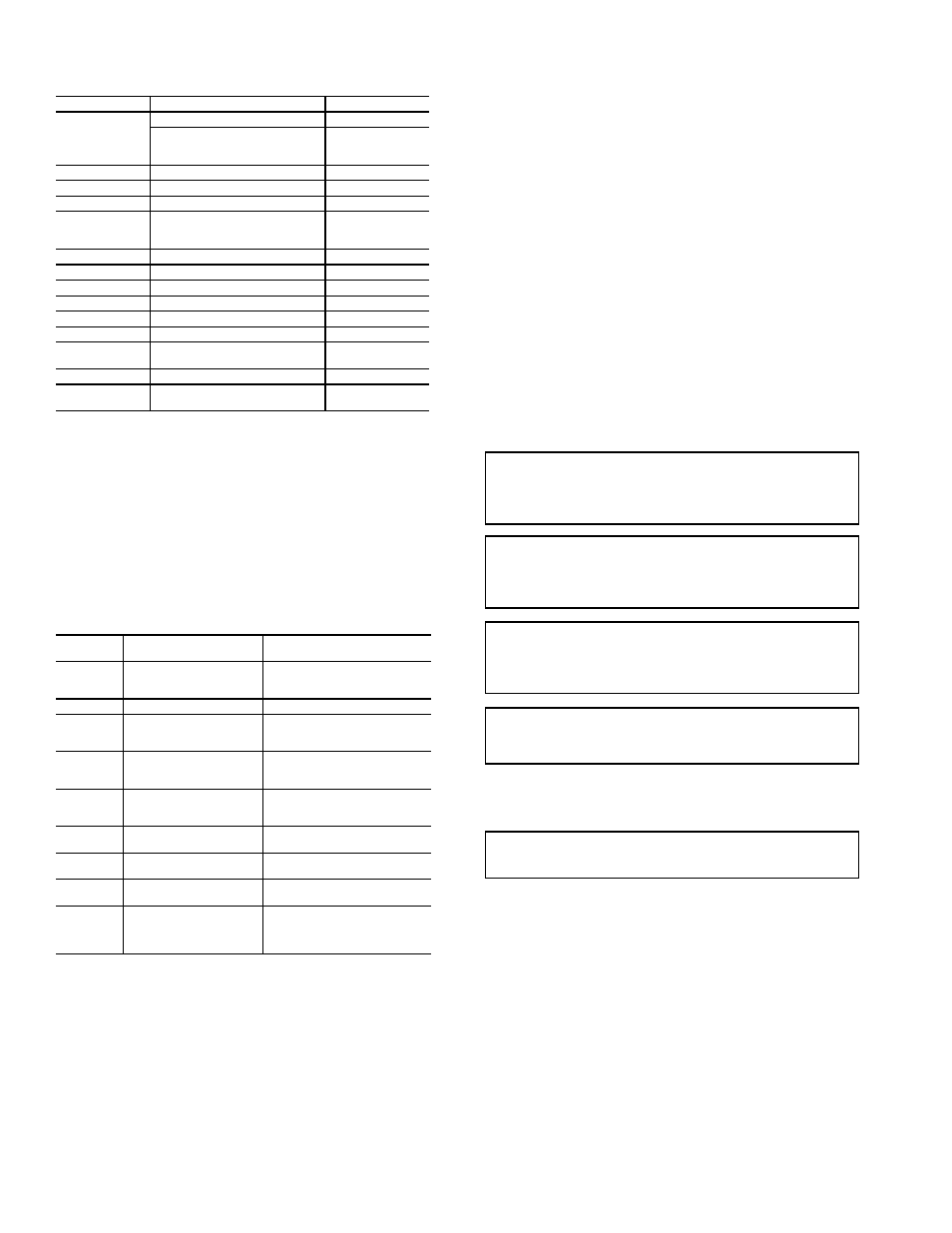
Table 19 — C Control Current LED Status
and Alarm Relay Operations
LEGEND
NOTES:
1. Slow flash is 1 flash every 2 seconds.
2. Fast flash is 2 flashes every 1 second.
3. EXAMPLE: “Flashing Code 2” is represented by 2 fast flashes followed by a
10-second pause. This sequence will repeat continually until the fault is
cleared.
Table 20 — C Control LED Code and
Fault Descriptions
LEGEND
Retry Mode —
In Retry mode, the status LED will start to
flash slowly to signal that the control is trying to recover from
an input fault. The control will stage off the outputs and try to
again satisfy the thermostat used to terminal Y. Once the ther-
mostat input calls are satisfied, the control will continue normal
operation.
NOTE: If 3 consecutive faults occur without satisfying the
thermostat input call to terminal Y, the control will go into
lockout mode. The last fault causing the lockout is stored in
memory and can be viewed by entering Test mode.
Aquazone™ Deluxe D Control LED Indica-
tors —
There are 3 LED indicators on the D Control:
STATUS LED — Status LED indicates the current status or
mode of the D control. The Status LED light is green.
TEST LED — Test LED will be activated any time the D
control is in test mode. The Test LED light is yellow.
FAULT LED — Fault LED light is red. The fault LED will
always flash a code representing the last fault in memory. If
there is no fault in memory, the fault LED will flash code 1 on
and appear as 1 fast flash alternating with a 10-second pause.
See Table 21.
SERVICE
Perform the procedures outlined below periodically, as
indicated.
Filters —
Filters must be clean for maximum performance.
Inspect filters every month under normal operating conditions.
replace when necessary.
Water Coil —
Keep all air out of the water coil. Check
open loop systems to be sure the well head is not allowing air
to infiltrate the water line. Always keep lines airtight.
Inspect heat exchangers regularly, and clean more frequent-
ly if the unit is located in a “dirty” environment. The heat
exchanger should be kept full of water at all times. Open loop
systems should have an inverted P trap placed in the discharge
line to keep water in the heat exchanger during off cycles.
Closed loop systems must have a minimum of 15 PSI during
the summer and 40 PSI during the winter.
Check P trap frequently for proper operation.
LED STATUS
DESCRIPTION OF OPERATION
ALARM RELAY
On
Normal Mode
Open
Normal Mode with
PM Warning
Cycle
(closed 5 sec.,
Open 25 sec.)
Off
C Control is non-functional
Open
Slow Flash
Fault Retry
Open
Fast Flash
Lockout
Closed
Slow Flash
Over/Under Voltage Shutdown
Open
(Closed after
15 minutes)
Flashing Code 1
Test Mode — No fault in memory
Cycling Code 1
Flashing Code 2
Test Mode — HP Fault in memory
Cycling Code 2
Flashing Code 3
Test Mode — LP Fault in memory
Cycling Code 3
Flashing Code 4 Test Mode — FP1 Fault in memory
Cycling Code 4
Flashing Code 5 Test Mode — FP2 Fault in memory
Cycling Code 5
Flashing Code 6
Test Mode — CO Fault in memory
Cycling Code 6
Flashing Code 7
Test Mode — Over/Under
shutdown in memory
Cycling Code 7
Flashing Code 8
Test Mode — PM in memory
Cycling Code 8
Flashing Code 9
Test Mode — Test Mode — FP1/
FP2 Swapped Fault in memory
Cycling Code 9
CO
— Condensate Overflow
FP
— Freeze Protection
HP
— High Pressure
LED — Light-Emitting Diode
LP
— Low Pressure
PM
— Performance Monitor
LED
CODE
FAULT
DESCRIPTION
1
No fault in memory
There has been no fault since
the last power-down to power-up
sequence
2
High-Pressure Switch
HP Open Instantly
3
Low-Pressure Switch
LP open for 30 continuous sec-
onds before or during a call
(bypassed for first 60 seconds)
4
Freeze Protection Coax
— FP1
FP1 below Temp limit for 30 con-
tinuous seconds (bypassed for
first 60 seconds of operation)
5
Freeze Protection Air Coil
— FP2
FP2 below Temp limit for 30 con-
tinuous seconds (bypassed for
first 60 seconds of operation)
6
Condensate overflow
Sense overflow (grounded) for
30 continuous seconds
7
(Autoreset)
Over/Under Voltage
Shutdown
"R" power supply is <19VAC or
>30VAC
8
PM Warning
Performance Monitor Warning
has occurred.
9
FP1 and FP2 Thermistors
are Swapped
FP1 temperature is higher than
FP2 in heating/test mode, or FP2
temperature is higher than FP1
in cooling/test mode.
FP
— Freeze Protection
HP
— High Pressure
LED — Light-Emitting Diode
LP
— Low Pressure
PM
— Performance Monitor
IMPORTANT: When a compressor is removed from this
unit, system refrigerant circuit oil will remain in the com-
pressor. To avoid leakage of compressor oil, the refrigerant
lines of the compressor must be sealed after it is removed.
IMPORTANT: All refrigerant discharged from this unit
must be recovered without exception. Technicians must fol-
low industry accepted guidelines and all local, state and fed-
eral statutes for the recovery and disposal of refrigerants.
IMPORTANT: To avoid the release of refrigerant into the
atmosphere, the refrigerant circuit of this unit must only be
serviced by technicians which meet local, state and federal
proficiency requirements.
IMPORTANT: To prevent injury or death due to electrical
shock or contact with moving parts, open unit disconnect
switch before servicing unit.
IMPORTANT: Units should never be operated with-
out a filter.