Dip switch settings – Steffes Transmitter User Manual
Page 8
I
NSTALLATION
C
ONTINUED
…
Anticipated Peak
Typically, power companies are capable of sending one signal for peak
control of selected devices. There are some instances; however, where
power companies are capable of sending multiple signals for control
purposes. In these situations, it is possible to have on-peak hours, off-peak
hours, and anticipated peak (pre-peak) hours.
On-peak hours are times during which a controllable load is disabled.
Off-peak hours are times during which a controllable load is allowed to
operate.
Anticipated (pre-peak) hours are times during which ETS
equipment can be prepared for an up coming on-peak (control) period, or a
time when power companies can apply customized control of the ETS
equipment.
Power companies selectively use anticipated peak (pre-peak) signals. If
uncertain as to whether this option is being utilized in your area, contact
your local power company representative.
DIP SWITCH SETTINGS
If the transmitter is being utilized with the Steffes 1000 and/or 2000 Series
heater(s), all dip switches on the heater’ s main control circuit board MUST
be set to the “ OFF” position except dip switches 5 and 7. These can be in
the “ OFF” or “ ON” position, depending on the application.
DIP SWITCH 1: INVERT PEAK
This dip switch is used to match the Steffes 1000, 2000, 2100 Series
room heaters, the Comfort Plus, or any device wired to the Steffes PLC
receiver for peak control purposes to the utility’ s signaling device.
FACTORY DEFAULT SETTING = ON
Off = An open utility switch signals an off-peak time to the heater
(charging is enabled in the ETS heater). A closed utility switch
signals an on-peak time (charging is disabled in the ETS
heater).
On = A closed utility switch signals an off-peak time to the heater
(charging is enabled in the ETS heater). An open utility switch
signals an on-peak time (charging is disabled in the ETS
heater).
D
IP
S
WITCH
S
ETTINGS
C
ONTINUED
… .
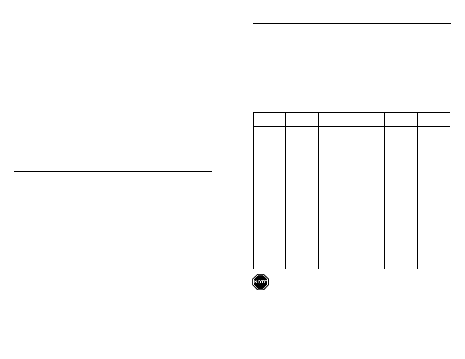
DIP SWITCH 2, 3, 4 and 5: TRANSMIT CHANNEL
The transmitter is capable of transmitting on one of fifteen channels. The
dip switch settings in the Steffes PLC transmitter MUST be set to match
the channel setting of the receiving device(s).
To select the power line carrier communication channel desired, use the
chart below and set dip switches 2, 3, 4 and 5 to the appropriate positions.
If dip switch 2, 3, 4, and 5 are all set to the "OFF" positions, the
transmitter will not transmit a power line carrier signal.
FACTORY DEFAULT = Channel One (2 ON, 3 OFF, 4 OFF, 5 OFF)
C
HANNEL
D
IP
S
WITCH
#2
D
IP
S
WITCH
#3
D
IP
S
WITCH
#4
D
IP
S
WITCH
#5
C
HANNEL
S
PEED
0
OFF
OFF
OFF
OFF
N/A
1
ON
OFF
OFF
OFF
SLOW
2
OFF
ON
OFF
OFF
SLOW
3
ON
ON
OFF
OFF
FAST
4
OFF
OFF
ON
OFF
FAST
5
ON
OFF
ON
OFF
FAST
6
OFF
ON
ON
OFF
FAST
7
ON
ON
ON
OFF
FAST
8
OFF
OFF
OFF
ON
FAST
9
ON
OFF
OFF
ON
FAST
10
OFF
ON
OFF
ON
FAST
11
ON
ON
OFF
ON
FAST
12
OFF
OFF
ON
ON
SLOW
13
ON
OFF
ON
ON
SLOW
14
OFF
ON
ON
ON
SLOW
15
ON
ON
ON
ON
SLOW
1. 1000/2000 Series heaters will ONLY receive on slow speed
channels.
2. If multiple transmitters are installed on the same
distribution transformer, do not use both channels one (1)
and two (2).
4
5