Steffes Transmitter User Manual
Page 4
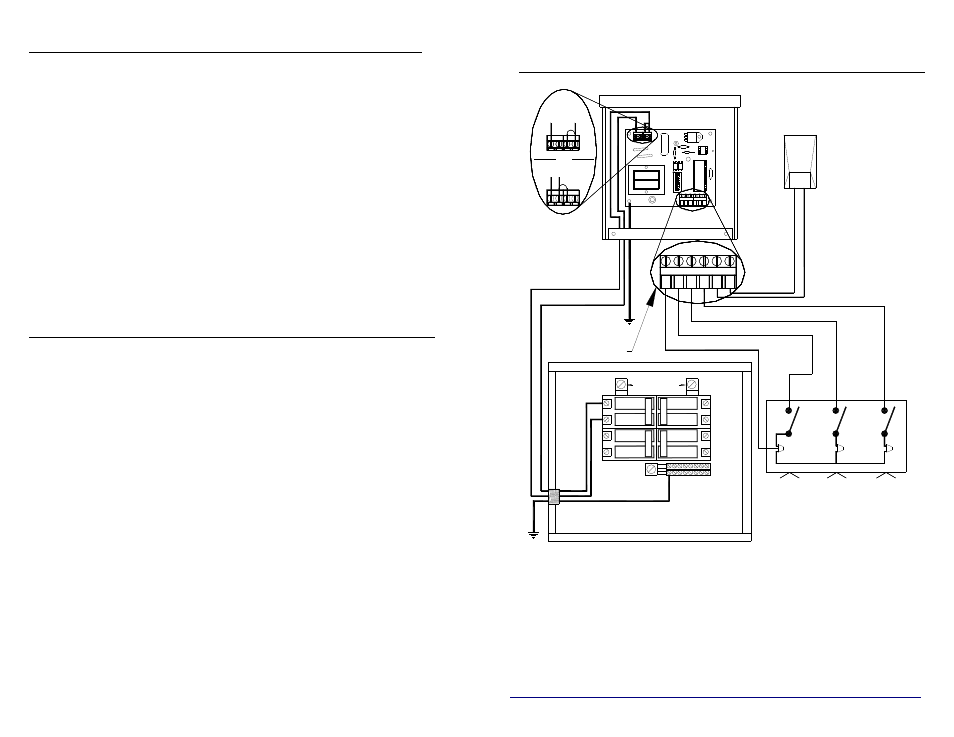
TABLE OF CONTENTS
General Operation...................................................................1
Installation............................................................................ 1-4
Line Voltage Connections ............................................... 1-2
Peak Control ........................................................................2
Circuit Board Configuration ................................................2
Outdoor Temperature Sensor...............................................3
Indicator Lights....................................................................3
Room Temperature Set Back...............................................3
Anticipated Peak ..................................................................4
Dip Switch Settings.............................................................. 4-6
Installer’s Final Check Out Procedure.............................. 7-8
Typical System Wiring Diagram (Single Phase)...................9
Typical System Wiring Diagram (3-Phase).........................10
FEATURES
The PLC transmitter is an accurate and reliable device offering the
following features:
w Operates on 120V or 208V/240V, single phase.
w Pre-wired 16 AWG leads for line voltage field connections.
w A 6” x 6” x 3” rainproof metal enclosure with power company
seal/lockout provision for indoor or outdoor installations. A three
phase system in a 12” x 6” x 3” rainproof metal enclosure is
available as a special factory order.
w Fifteen (15) selectable communication channels.
w Wireless control of an unlimited number of Steffes microprocessor
based heating systems and any controllable devices with the
correlating receiver.
w Capable of transmitting:
é Peak Control Signals
é Outdoor Temperature Information (Automatic Charge Control)
é Room Temperature Set Back Information (requires an external
signaling device, not included)
é Anticipated Peak (pre-peak) Control Signals
TYPICAL SYSTEM WIRING DIAGRAM
SINGLE PHASE (208/240 Volt or 120 Volt)
NOTES:
1. To ensure proper communications between the PLC transmitter and the
controllable electrical loads, the transmitter MUST be grounded.
2. The system grounding and bonding must be sized and installed in
compliance with all applicable codes.
3. The transmitter in this diagram is shown connected directly to the service
panel. However, any appropriately sized uninterrupted branch circuit
can be used to power the transmitter
2
1
4
5
6
7
8
3
E
ROOM TEMP SETBACK (OPTIONAL)
A-PEAK (SPECIAL APPLICATIONS)
LOW VOLTAGE HOT
208/240V
LOW VOLTAGE
CONNECTIONS
20
20
15
2
20
1
240VAC SOURCE
R
R
O
C
K
ER
D
O
W
N
120V
OR
N O
LINE
VOLTAGE
CONNECTIONS
SENSOR
Power Company.
Set-Back
Room
4
3
Anticipated Peak
Control Switch.
Utilized By the
Control Switch.
Utility Peak
PEAK
SENSOR
OUTDOOR
A
P
O
S
O
S
(OPTIONAL)
OUTDOOR
REMOTE
( Optional )
Temperature
Only if being
Service Panel
9