Important, Warning – Steffes Transmitter User Manual
Page 3
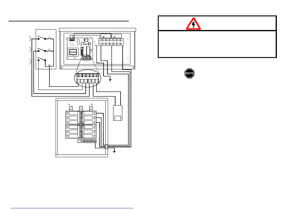
TYPICAL SYSTEM WIRING DIAGRAM
208/240 VOLT, 3-PHASE SYSTEMS ONLY
NOTES:
1. To ensure proper communications between the PLC transmitter and the
controllable electrical loads, the transmitter MUST be grounded.
2. The system grounding and bonding must be sized and installed in
compliance with all applicable codes.
3. The transmitter in this diagram is shown connected directly to the service
panel. However, any appropriately sized uninterrupted branch circuit
can be used to power the transmitter.
20
A
3
-P
H
A
SE
20
A
3
-P
H
A
SE
20
A
3
-P
H
A
SE
15
A
3
-P
H
A
SE
2
4
240/208VAC SOURCE
1
3-PHASE
3
O
S
CONNECTIONS
LOW VOLTAGE
R
E
A
P
4
5
6
N O
2
3
1
R
O
C
K
ER
D
O
W
N
7
8
O
S
2
E
N
I
L
1
E
N
I
N
U
O
R
L
G
D
3
E
N
I
L
1 5 5 K
630V
H.
.M
.M
1 5 5 K
H.
630V
REMOTE
OUTDOOR
(OPTIONAL)
SENSOR
Room Temperature
Set-Back. ( Optional )
Utility Peak
Control Switch.
Power Company.
Switch. Only if being
Anticipated Peak Control
Utilized By the
ROOM TEMP SETBACK (SPECIAL APPLICATIONS)
A-PEAK (OPTIONAL)
LOW VOLTAGE HOT
PEAK
Service Panel
IMPORTANT
w
The equipment described herein is intended for installation by a
qualified technician in accordance with applicable local, state, and
national codes and requirements.
w
This manual should be retained by the owner upon completion of the
installation and made available to service personnel as required.
w
Disclaimer:
Conditions may occur which cause the power line carrier
transmitter and receivers to have difficulties communicating;
therefore, not operating properly. In no event shall Steffes
Corporation be liable for any indirect, special, or consequential
damages or lost profits.
In compiling this manual, Steffes Corporation has used its best
judgement based upon information available, but disclaims any
responsibility or liability for any errors or miscalculations
contained herein, or any revisions hereof, or which result, in
whole or in part, from the use of this manual or any revisions
hereof.
WARNING
HAZARDOUS VOLTAGE: Risk of electric shock, injury, or
death. System may be connected to more than one branch
circuit. Disconnect power to all circuits before servicing.
Equipment must be installed and serviced by a qualified
technician.
F
OR
C
USTOMER
U
SE
Please record the serial number of the transmitter below. This information is
located inside the transmitter enclosure. Retain this information for future
reference.
Serial No.________________________________________________
10