Installer’s final check out procedure, Peak control, Circuit board configuration – Steffes Transmitter User Manual
Page 6
I
NSTALLATION
C
ONTINUED
…
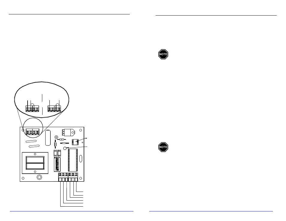
If the transmitter is to be connected to 120V, transformer tapping
MUST be changed. To change transformer tapping to 120V, move the
black wire jumper to positions P2 and 110 in the line voltage terminal
strip. Move the factory installed line voltage connections to the 110 and
L1 positions in the line voltage connections terminal strip. (See Circuit
Board Configuration below for reference to proper placement of the
jumper and wires.)
Peak Control
Connect the peak control signaling device to the "R" and "P" terminals
on the low voltage terminal strip.
Circuit Board Configuration
INSTALLER’S FINAL CHECK OUT PROCEDURE
____ 1.
Prior to energizing the electrical circuit feeding the transmitter,
inspect all field installed electrical connections to ensure they are
tight and all wires are routed correctly. All line voltage wiring
connections must be made within and routed through the line
voltage raceway of the factory-installed junction box. To ensure
proper communication, the transmitter must be grounded.
The transmitter is factory configured for 208V/240V field
connections. If using 120V input, transformer tapping must
be changed. (Refer to the Circuit Board Configuration
Diagram.)
____ 2. Make sure
the dip switch settings on the transmitter are in the
correct positions for the application. Remember, the desired PLC
channel MUST be selected for communication to occur.
____ 3.
Activate the utility peak control device and energize the
transmitter. Verify that the indicator light on the transmitter is
illuminated and corresponds with the utility peak signal (flashing
for off-peak or continuous illumination for on-peak).
____ 4.
Invert dip switch #1 on the transmitter. If the indicator light was
flashing in Step 3, it should now illuminate continuously. If the
light had been illuminated, it should now begin to flash. Return
dip switch #1 to the proper position for the application.
____ 5.
Use the guidelines which follow to verify the transmitter is
communicating with all receivers in the application
(microprocessor based heaters and Steffes mini receiver
configurations).
Communication between the transmitter and receiver
occurs on a continuous basis. Upon energizing a system,
there will be some delay in a receiver’s response to the
transmitter's signal. It takes approximately seven (7)
minutes to establish initial communication. Subsequent
communication will occur more rapidly.
INTERFACING THE TRANSMITTER WITH THE STEFFES MINI
RECEIVER (single, double or six pole configurations):
Once the mini receiver is receiving complete information from the
transmitter, the red indicator light on the mini receiver will illuminate
continuously. Refer to the Operation and Installation Guide for the Mini
Receiver to perform the checkout procedure for this device and ensure
correct installation and operation.
2
7
SO
FT
W
A
R
E
R
O
C
K
E
R
D
O
W
N
5
6
7
8
O
N
1
2
3
4
TRANSFORMER
M
IC
R
O
PR
O
C
E
SS
O
R
CHIP
MEMORY
L2
L1 L2
L1
OR
P2
22
0
11
0
L
1
LINE
VOLTAGE CONNECTIONS
120V
208V/240V
INDICATOR
LIGHT
OS - OUTDOOR SENSOR
A - ANTICIPATED PEAK
P - PEAK CONTROL
R - LOW VOLTAGE HOT
E - ROOM TEMP. SET BACK
OS - OUTDOOR SENSOR
Low Voltage
Terminal Strip Connections