Yamaha, Operation, Midi data format – Yamaha MFC06 User Manual
Page 2: Specifications
Attention! The text in this document has been recognized automatically. To view the original document, you can use the "Original mode".
© After making sure that both the MFC06 power switch and the
FX500 power switch are OFF, connect an appropriate MIDI cable
(less than 15 meters) from the MFC06 MIDI OUT connector to the
MIDI IN connector on the FX500.
© First turn the MFC06 power switch ON, and then the power switch
of the FX500. When the MFC06 power switch is turned ON, the
"PGM" LED indicator will light.
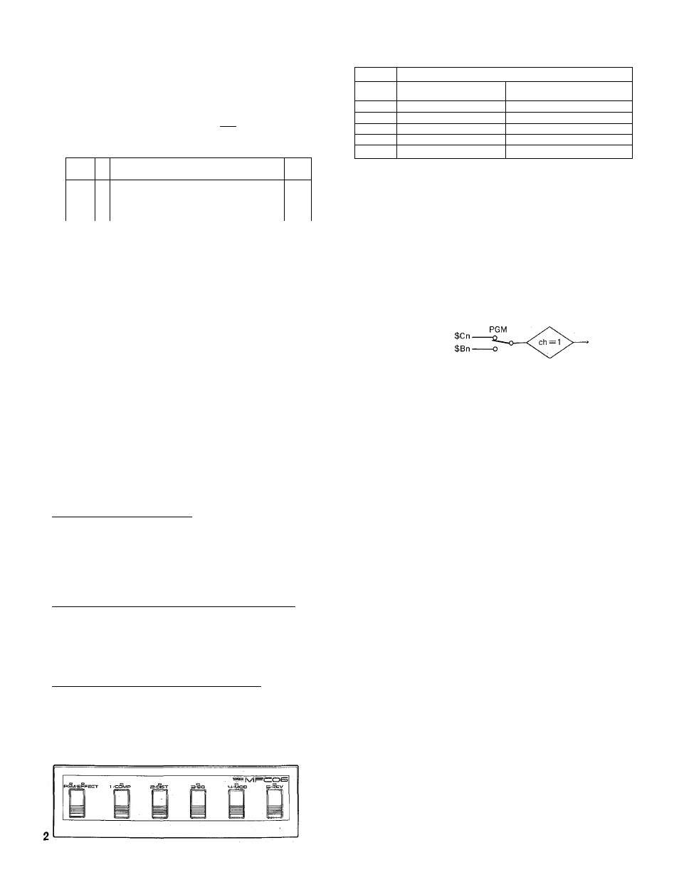
t n I®
YAMAHA
)o
1__f 1—1 ' 1____________ 1 1_______ f \______ 1
1
1
__________ ___________ 1
1—
J
@
® Set the receive channel of the FX500 "BANK" (A, B, C or D) you
intend to use to "1" or "OMNI." Refer to your FX500 operation
manual for details. The MFC06 transmits only on channel 1.
© Since the MFC06 transmits MIDI program change numbers 1
through 5, make sure the FX500 program change assignment
table for the selected BANK is set up so that these program
numbers select the desired FX500 effect programs.
If, for example, you want the 5 MFC06 footswitches to select
FX500 programs 61 through 65, the FX500 program change
assignment table for the BANK to be used should be set up as
follows:
BANK A,B,CorD.
ch = 1 or OMNI
PGM 1 = MEN 61
PGM 2 = MEM 62
PGM 3 = MEM 63
PGM 4 = MEM 64
PGM 5 = MEM 65
OPERATION
PGM/EFFECT Footswitch & Indicators
The PGM/EFFECT footswitch determines whether the five selector
footswitches (1/COMP — 5/REV) will transmit MIDI program change
numbers 1 through 5, thereby selecting the corresponding FX500
programs (PGM), or whether the footswitches will turn the corresponding
FX500 effect stages ON and OFF (EFFECT). The "PGM" or "EFFECT"
indicator will light to show which function is currently selected.
PGM MODE: 1/COMP — 5/REV Selector Footswitches & Indicators
When the PGM mode is selected (i.e. the PGM/EFFECT footswitch
"PGM" indicator is lit), footswitches 1/COMP through 5/REV cause
transmission of the corresponding program change numbers. The LED
indicator above the most recently pressed footswitch lights to show which
program number was selected.
EFFECT MODE: 1/COMP — 5/REV Selector Footswitches
When the EFFECT mode is selected (i.e. the PGM/EFFECT footswitch
"EFFECT" indicator is lit), footswitches 1/COMP through 5/REV cause
the corresponding FX500 effect stage to be turned ON or OFF, depending
on its current corxfition. If the selected stage is ON, pressing the
corresponding footswitch will turn it OFF, and vice-versa. The selector
footswitch indicators do not light when the EFFECT models selected.
PGM/EFFECT MODE SWITCH
SELECT
SWITCH
PGM
EFFECT
1/COMP
PGM NO. 1 TRANSMITTED
COMPRESSOR STAGE ON/OFF
2/DIST
PGM NO. 2 TRANSMITTED
DISTORTION STAGE ON/OFF
3/EQ
PGM N0.3 TRANSMITTED
EQUALIZER STAGE ON/OFF
4/MOD
PGM NO. 4 TRANSMITTED
MODULATION STAGE ON/OFF
5/REV
PGM NO. 5 TRANSMITTED
REVERB STAGE ON/OFF
NOTE: The MFC06 actually transmits MIDI program change numbers
0 through 4, but these correspond to FX500 PGM numbers 1
through 5.
NOTE: No MIDI data is transmitted when the PGM/EFFECT
footswitch is pressed. The appropriate MIDI message is
transmitted only when one of the selector footswitches
(1/COMP — 5/REV) is pressed.
MIDI DATA FORMAT
1. TRANSMISSION CONDITIONS
PROGRAM CHANGE
CONTROL CHANGE
MIDI OUT
EFFECT
2. TRANSMISSION DATA
Channel Information (Channel Voice Message)
PROGRAM CHANGE
STATUS
PROGRAM NO.
STATUS
CONTROL NO.
CTRL VALUE
1 10 0 0 0 0 0 (COH)
O O O O p p p p
p = 0(PGM1)-
-4 (PGM no. 5)
1 01 1 0 0 0 0 (BOH)
O c c c c c c c
c = 116 (COMP) —120 (REV)
O v v v v v v v
v = 0 (OFF), 127 (ON)
SPECIFICATIONS
Transmitted Data
PGM MODE: MIDI program change messages 0
(PGM 1) through 4 (PGM 5).
EFFECT MODE; MIDI control change messages
116(COMP) through 120 (REV).
MIDI Transmit Channel
Channel 1 only.
Indicators
PGM, EFFECT, 1/COMP, 2/DIST, 3/EQ, 4/MOD,
5/REV.
Switches
PGM/EFFECT, 1/COMP, 2/DIST, 3/EQ, 4/MOD,
5/REV, POWER.
Connectors
MIDI OUT, DC9V—12V IN.
Power Source
AA dry battery x 6, or PA-1(B) AC adapter.
Battery Life
Approximately 10 hours continuous
(alkaline batteries).
Dimensions
444 mm
X
41 mm
X
130 mm
( W x H x D )
(17-1/2"
X
1-5/8"
X
5-1/8")
Weight
1.2 kg. (2.6 lbs.) Incl. batteries.
Supplied Accessories
One set of six AA batteries.
Optional Accessories
PA-1 or PA-1 B AC Adapter.
SERVICE
This product is supported by Yamaha's worldwide network of factory trained
and qualified dealer service personnel.
In the event of a problem, contact your nearest Yamaha dealer.