CANOGA PERKINS 9145 NID User Manual
Quick start guide 9145 nid
Quick Start Guide
9145 NID
Canoga Perkins Corporation, 20600 Prairie Street, Chatsworth, CA 91311-6008
Phone: (818) 718-6300, FAX (818) 718-6312 www.canoga.com
P/N 6943300 Rev A
Page 1 of 8
Overview
This document provides instructions for installation and initial configuration of the Canoga
Perkins model 9145 NID (Network Interface Device).
Parts List
1 x 9145-4 (AC power) or 9145-5 (DC power)
1 x User (USR) port interface module (typically a UTP module, but can also be an optical
module)
1 x Extension (EXT) port interface module (typically an optical module)
1 x Set of 19” or 23” optional rack mount ears
1 x AC power cord
Tools Required
1 x EIA-232 DB-9 cable (not included)
1 x Phillips/flat screwdriver (if mounting in a relay rack)
Step 1: Unpacking
Unpack the 9145 and check the unit for damage. If the unit is damaged, contact Canoga Perkins’
Tech Support line, (800) 360-6642, and ask for an RMA.
Step 2: Module Insertion
It is very likely that the USR and EXT ports are already occupied by the correct interfaces for the
application from the factory. However, if the interfaces are ordered separately, follow the next
steps to configure the modules.
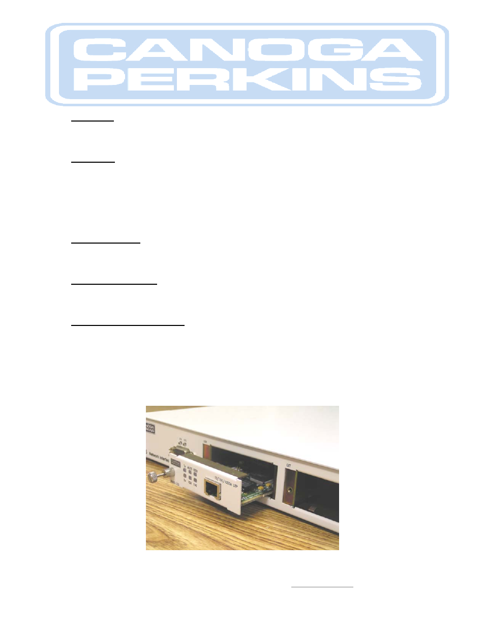
Insert the user interface module in the USR port/slot of the NID. The module should slide into
the slot with ease and make contact with the rear connector without excessive force. Tighten the
thumbscrew and do the same for the EXT port.
Figure 1. 10/100/1000Base-T UTP module insertion in USR port