5 port default settings, 6 power connectors, 1 power requirements – CANOGA PERKINS 9145E Ethernet Network Interface Device Hardware User Manual
Page 21: 2 single ac power base unit
Functional Description
9145E Ethernet Network Interface Device User’s Manual
Port Default Settings
9
2.5 Port Default Settings
Table 2-2 represents the default settings for each of the ports. The term active connector refers to
the connector, either UTP or SFP, that is currently enabled. For example, if a particular 9145E
model has a User Port with both UTP and SFP connectors present, by default the UTP is the
Active Connector (it can currently transmit and receive data), while the SFP is the Inactive Con-
nector (i.e., it currently cannot transmit or receive data).
Table 2-2. Default Port Settings
NOTE:Cells in yellow denote which of the connectors are active by default
2.6 Power Connectors
The 9145E will accommodate both single and redundant AC and DC powering options, along
with mixed AC and DC power.
2.6.1 Power Requirements
100 VAC to 240 VAC (auto-ranging), 50 to 60 Hz, 0.5 amps
36 VDC to 72 VDC, 1.0 amps
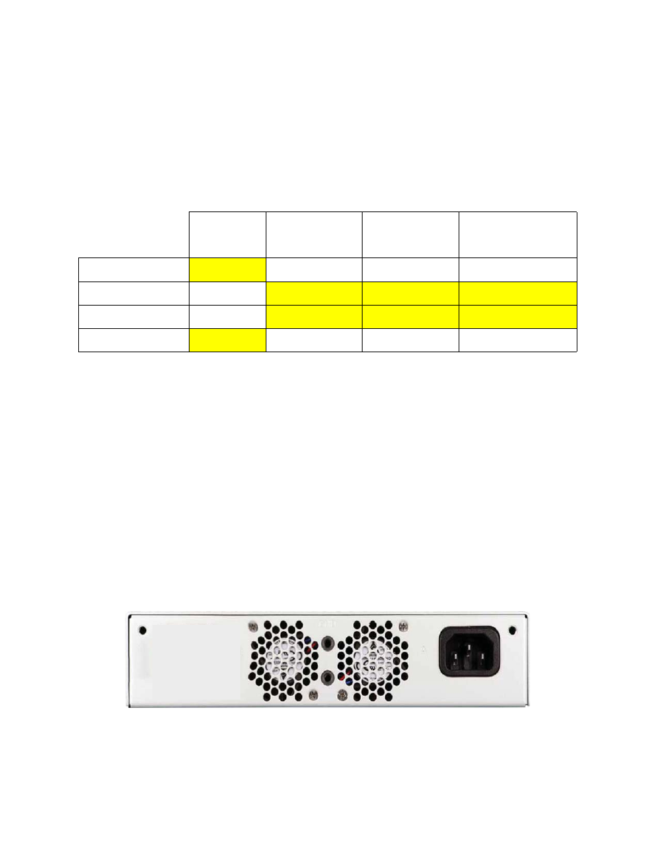
2.6.2 Single AC Power Base Unit
The Single AC powered 9145E base unit (see Figure 2-3) has an IEC 320 power connector on
the rear panel. An appropriate AC power cord is supplied with the unit.
Figure 2-4. Single AC Power
UTP
SFP w/ 100
Mbps Optics
SFP w/ 1000 Mbps
Optics
SFP w/ Multispeed
Optics (100 to 1000)
User Port
Auto
100 FD
1000 FD
1000 FD
Network Port
Auto
100 FD
1000 FD
1000 FD
Multipurpose Port
Auto
100 FD
1000 FD
1000 FD
Mgmt UTP port
Auto
N/A
N/A
N/A