2 hardware configuration, 1 front panel – CANOGA PERKINS 9145E Ethernet Network Interface Device Hardware User Manual
Page 18
9145E Ethernet Network Interface Device User’s Manual
Functional Description
Hardware Configuration
6
2.2 Hardware Configuration
The 9145E can be ordered with different port and connector options.
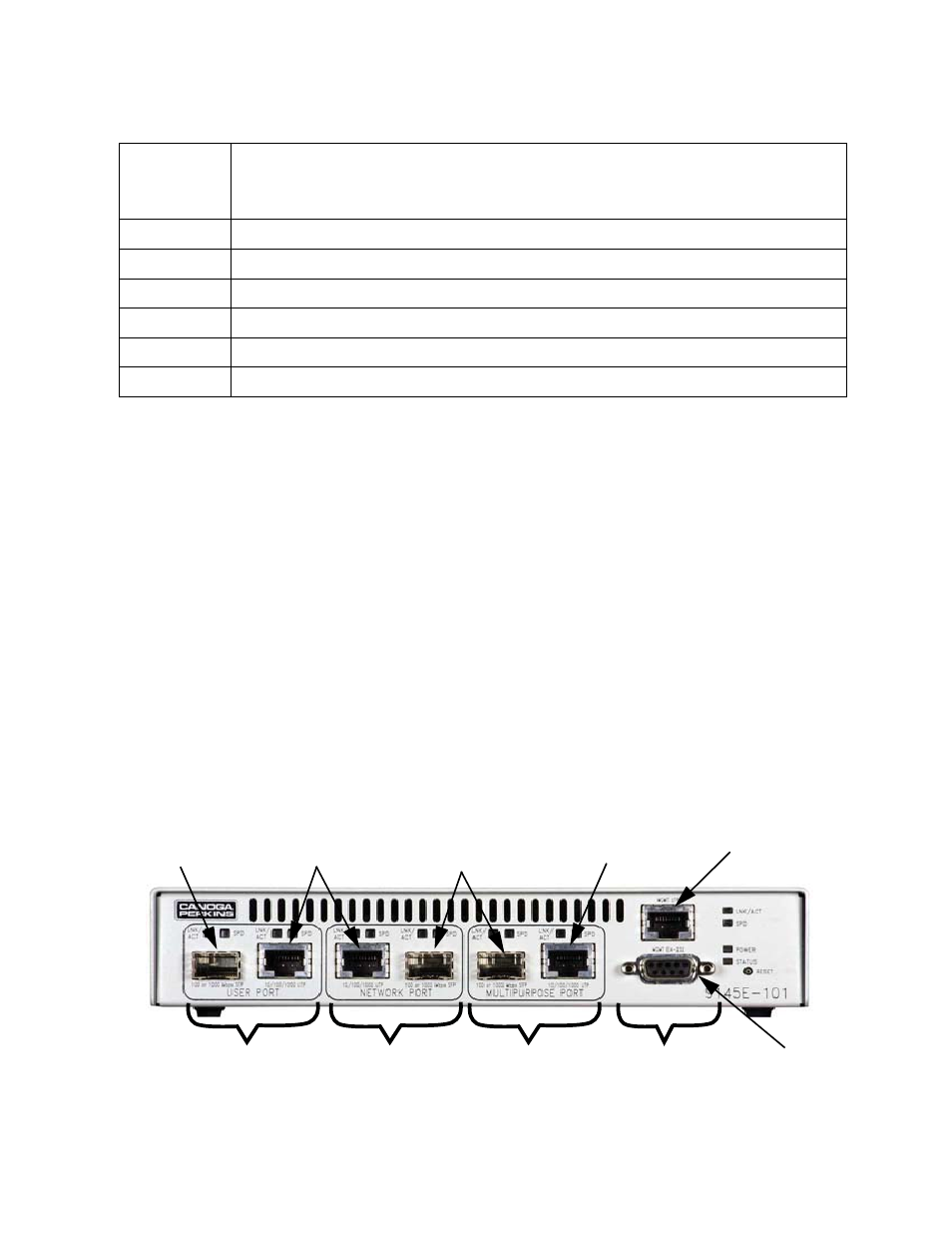
2.2.1 Front Panel
The 9145E has a variety of models and configurations (see Table 2-1). Customers can choose a
model depending on the application.
1. One EIA-232 console port with DE-9 female connector
2. One Ethernet Management Port with UTP connector
3. One User Port (for service data) with both SFP and UTP connectors
4. One Network Port (for service data) with both SFP and UTP connectors
5. One Multi-Purpose Port (service data and/or management traffic) with both SFP and UTP
connectors
9145E-203-8-0
V2 Engine, UTP/SFP User Port, UTP/SFP Network Port, Redundant 48VDC Power Supply
9145E-203-9-0
V2 Engine, UTP/SFP User Port, UTP/SFP Network Port, Redundant AC/48VDC Power Supply
9145E-204-5-0
V2 Engine, UTP/SFP User Port, UTP/SFP Network Port, Single AC Power Supply
9145E-204-6-0
V2 Engine, UTP/SFP User Port, UTP/SFP Network Port, Single 48VDC Power Supply
9145E-204-7-0
V2 Engine, UTP/SFP User Port, UTP/SFP Network Port, Redundant AC Power Supply
9145E-204-8-0
V2 Engine, UTP/SFP User Port, UTP/SFP Network Port, Redundant 48VDC Power Supply
9145E-204-9-0
V2 Engine, UTP/SFP User Port, UTP/SFP Network Port, Redundant AC/48VDC Power Supply
Table 2-1. 9145E Model Numbers and Configuration
MODEL
NUMBER
EXTENDED DESCRIPTION
USER
PORT
NETWORK
PORT
MULTIPURPOSE
PORT
MANAGEMENT
PORTS
SFP
CONNECTOR
SFP
CONNECTOR
UTP
CONNECTOR
UTP
CONNECTOR
ETHERNET
MANAGEMENT
PORT
EIA-232
CONSOLE
PORT