3 main menu, 3 main menu -3, Figure 23. the modem main menu screen -3 – CANOGA PERKINS 2461 E1 Modem User Manual
Page 33: Table 2. eia-232 de 9 pin-out -3
EdgeAccess Universal Chassis System
When the switch position is TRM, the interface is a DCE, and the I/O assignments for the 9-pin
serial port EIA-232 interface (on the stand alone modem) are:
Table 2: EIA-232 DE-9 pinout
Signal name
Pin Number
Source I/O
TXD
3
DTE Input
RXD
2
DCE Output
RTS
7
DTE I
CTS
8
DCE O
DTR
4
DTE I
DSR
6
DCE O
DCD
1
DCE O
RI
9
DCE O
SIG GND 5 ----- -----
Note the 9-pin serial port on the stand alone modem can be configured as a DTE. This permits
connection to a serial port on a typical dial-up modem device.
For accessing the terminal screens through the DMM, please consult the DMM manual regarding
two important issues
• Accessing a specific modem's menu screens via the DMM
• Viewing a specific modem within the UCS
Using the DMM screen, you must first access the Chassis that the modem resides in,
then access the slot number for the modem. You'll then see the same terminal screens
as if you had interfaced to the modem directly.
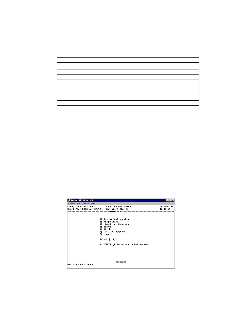
4.3 Main Menu
Once the correct chassis and slot number is accessed via the DMM or direct connection to the
modem, the modem's Main Menu screen will appear.
Figure 23. The Modem Main Menu screen
2461 Modem User Manual
4-3